cuisinart pressure cooker user manual

Welcome! This guide unlocks the potential of your Cuisinart electric pressure cooker, offering safe and efficient cooking. Explore manuals, recipes, and troubleshooting tips for optimal use.

Cuisinart provides comprehensive resources, including downloadable PDFs from the Internet Archive and ManualsLib, ensuring a smooth cooking experience.

Understanding the Benefits of Pressure Cooking

Pressure cooking dramatically reduces cooking times, offering a convenient solution for busy lifestyles. Utilizing higher temperatures achieved within a sealed environment, food cooks significantly faster than conventional methods.

Cuisinart pressure cookers retain more nutrients, flavors, and aromas compared to other cooking techniques. This is because less water is used, minimizing nutrient loss through evaporation.

Furthermore, pressure cooking excels at tenderizing tougher cuts of meat, transforming them into succulent and flavorful dishes. The sealed environment also minimizes odors, keeping your kitchen fresh. Explore the included recipe booklet and online resources to discover the versatility of your Cuisinart appliance!

Cuisinart Pressure Cooker Models Covered

This guide provides instructions applicable to a range of Cuisinart electric pressure cooker models, ensuring broad usability. Specifically, we will focus on the CPC-600 Series, including variations like the CPC-610XA, offering detailed control panel explanations and operational guidance.

Additionally, information is included for the more advanced EPC-1200PC Series, addressing its unique features and functionalities. Downloadable manuals from resources like ManualsLib cover the EPC-1200PC and related models, providing comprehensive support.

While slight variations may exist between specific sub-models, the core principles and operating procedures remain consistent, allowing you to confidently utilize your Cuisinart pressure cooker.

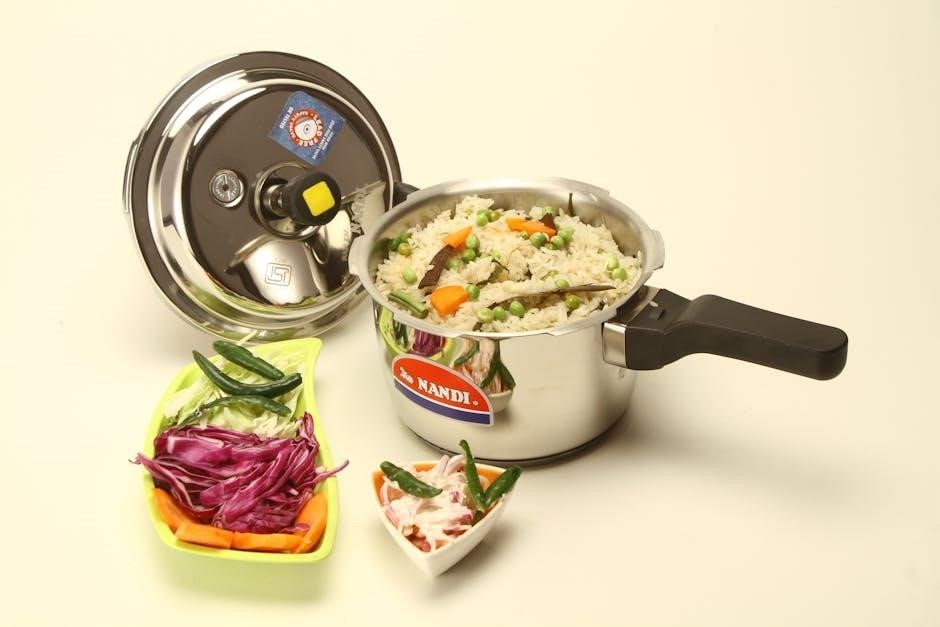
Key Components and Parts

Familiarize yourself with essential parts: the lid with its sealing ring, the inner cooking pot, and the control panel – differing between series (CPC-600 & EPC-1200PC).

Pressure Cooker Lid and Sealing Ring

The lid is crucial for building and maintaining pressure, ensuring safe operation. Always inspect it before each use, verifying it’s clean and free from damage. The sealing ring, typically made of silicone, creates an airtight seal between the lid and the cooker body.

Proper sealing is vital; a damaged or improperly seated ring will prevent pressure from building. Regularly check the sealing ring for cracks, tears, or deformation. Replacement is necessary when these issues arise, ensuring optimal performance and safety. Refer to your model’s manual for specific sealing ring replacement instructions.

Ensure the lid is correctly locked into place before starting any pressure cooking cycle. Incorrect locking can lead to pressure leaks and potential hazards.
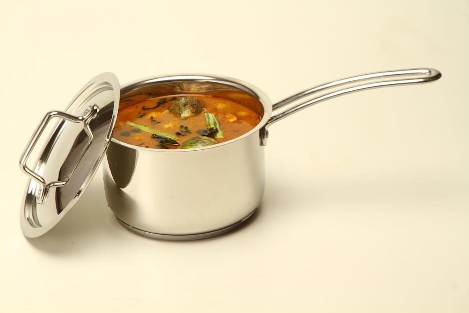
Inner Cooking Pot

The inner cooking pot is the removable vessel where food is placed for pressure cooking. Typically constructed from stainless steel or a non-stick material, it distributes heat evenly for consistent cooking results. Before each use, ensure the pot is clean and free of any food residue.

Always use the pot designed specifically for your Cuisinart pressure cooker model. Using an incompatible pot can compromise safety and performance. When adding liquids, adhere to the minimum and maximum fill lines indicated inside the pot to prevent issues like food burning or pressure build-up problems.

Carefully remove the pot after pressure has been naturally released or manually released following the manufacturer’s instructions.

Control Panel Overview (CPC-600 Series)

The CPC-600 series control panel features a digital display and several buttons for operation. Key functions include ‘Pressure Cook’, ‘Sauté/Brown’, and ‘Slow Cook’. Use the ‘Timer’ buttons to adjust cooking times, and the ‘Pressure Level’ button to select high or low pressure.

The ‘Start’ button initiates the selected cooking program, while ‘Cancel’ stops it. A ‘Warm’ function automatically activates after cooking is complete, keeping food at a serving temperature. Refer to your user manual for specific button functions and programming sequences.

Familiarize yourself with the panel’s indicators, such as the ‘Lid Lock’ and ‘Pressure’ lights, to monitor the cooker’s status.

Control Panel Overview (EPC-1200PC Series)

The EPC-1200PC series boasts an advanced electronic control panel. It includes pre-set programs for various foods like poultry, beef, and beans, simplifying cooking. The digital display clearly shows cooking time and pressure level.

Key buttons include ‘Pressure Cook’, ‘Sauté’, ‘Slow Cook’, and ‘Steam’. Use the ‘Timer’ and ‘+/–’ buttons to customize settings. A dedicated ‘Keep Warm’ function maintains food temperature post-cooking. The ‘Cancel’ button halts operation immediately.

Pay attention to indicator lights for ‘Lid Locked’, ‘Pressure’, and ‘Heating’ to ensure safe and efficient operation. Consult your instruction booklet for detailed program guides.

Getting Started: Initial Setup

Before first use, thoroughly clean the inner pot, lid, and sealing ring. Perform a water test to verify proper sealing and functionality, as per the manual.

First-Time Use: Cleaning and Testing

Prior to your inaugural cooking session, meticulous cleaning is paramount. Remove all packaging materials and wash the inner cooking pot, pressure cooker lid, and sealing ring with warm, soapy water. Ensure a thorough rinse and complete drying.

Crucially, perform a water test. Add 2 cups of water to the inner pot, close and lock the lid securely. Select the ‘Pressure Cook’ function on the control panel, setting it for 5 minutes. Allow the pressure to release naturally.

This test confirms proper sealing and functionality of the pressure cooker. If the unit fails to pressurize or leaks steam, revisit the lid sealing instructions in your user manual before proceeding. This initial test guarantees safe and effective operation.

Understanding Safety Features

Your Cuisinart pressure cooker is equipped with multiple safety mechanisms designed to prevent accidents and ensure secure operation. These include a locking lid that prevents opening during pressure, and a safety valve to release excess pressure if the primary valve malfunctions.

The ‘Lid’ error message indicates improper lid closure, preventing pressurization. Never force the lid open; ensure complete pressure release first. Familiarize yourself with the steam release methods – natural release and quick release – detailed in the manual.

Always adhere to maximum fill lines indicated within the inner pot to avoid blockage and potential hazards. Regularly inspect the sealing ring for cracks or damage, replacing it as needed for optimal performance and safety.

Operating Instructions

Mastering your Cuisinart involves understanding functions like pressure cooking, sautéing, slow cooking, and steaming. Refer to the manual for precise instructions and recipes!

Pressure Cooking Function

Utilizing the pressure cooking function significantly reduces cooking times while preserving flavors and nutrients. Begin by ensuring sufficient liquid is in the inner pot – a minimum amount is crucial for proper pressure build-up. Securely lock the lid, verifying the sealing ring is correctly positioned.

Select your desired pressure level (high or low) and cooking time using the control panel. The cooker will automatically maintain pressure throughout the set duration. Once complete, allow for natural pressure release or carefully use the quick release valve, following safety guidelines detailed in your user manual. Remember to always consult the recipe for specific pressure cooking instructions and timings.

Sauté/Brown Function

The Sauté/Brown function allows for searing meats and vegetables directly within the pressure cooker pot, eliminating the need for separate cookware. This feature is ideal for developing rich flavors before pressure cooking. Select the “Sauté” setting on the control panel, and the cooker will heat the inner pot.

Add oil and your ingredients, browning them to your preference. Be mindful of sticking and stir frequently. Once browned, you can proceed directly to pressure cooking without transferring the ingredients. Always ensure sufficient liquid is added before sealing the lid for pressure cooking, as the sautéing process may reduce initial liquid levels.

Slow Cooking Function

The Slow Cooking function offers a convenient alternative to traditional slow cookers, allowing for long, gentle cooking to tenderize tougher cuts of meat and develop deep flavors. Select the “Slow Cook” setting on your Cuisinart pressure cooker. You can typically choose from Low, Medium, or High heat settings, depending on your model.

Ensure ingredients are added with sufficient liquid. Unlike pressure cooking, the lid can be placed on loosely or not at all during slow cooking. Cooking times will vary based on the recipe and selected heat level, often ranging from several hours to overnight for optimal results.
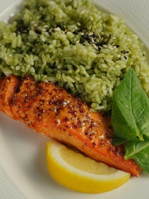
Steam Function

Utilizing the Steam function allows for healthy and efficient cooking of vegetables, seafood, and even desserts. Ensure the inner pot contains at least one cup of water. Place the steaming rack inside the pot, and arrange your food on the rack, preventing direct contact with the water.

Secure the lid, ensuring the steam release valve is in the ‘Sealing’ position. Select the ‘Steam’ function and adjust the cooking time according to your recipe. This method preserves nutrients and flavors, delivering perfectly steamed dishes. Remember to carefully release the pressure after steaming is complete.

Recipes and Cooking Times

Discover delicious possibilities! Explore poultry, beef, pork, and vegetable recipes tailored for your Cuisinart pressure cooker, with precise cooking times for perfect results.

Poultry Recipes

Unlock flavorful poultry dishes with ease! Your Cuisinart pressure cooker dramatically reduces cooking times while preserving moisture and tenderness. Consider a classic whole chicken – achieve fall-off-the-bone perfection in under an hour, compared to traditional roasting methods.

Explore recipes for chicken thighs, breasts, and even wings. Utilize the pressure cooking function for incredibly tender results. Remember to adjust liquid levels based on the recipe and your cooker model (CPC-600 or EPC-1200PC).

Online resources and included recipe booklets offer guidance on seasoning, ingredient combinations, and precise cooking durations. Always prioritize safety and follow recommended guidelines for poultry preparation.

Beef and Pork Recipes

Transform tough cuts into tender masterpieces! The Cuisinart pressure cooker excels at breaking down connective tissues in beef and pork, delivering incredibly flavorful results. Explore recipes for pot roast, pulled pork, and short ribs – all achievable in a fraction of the usual time.

Utilize the sauté function to brown meats before pressure cooking, enhancing depth of flavor. Remember to adjust cooking times based on the cut and weight of the meat. Consult your user manual (CPC-600 or EPC-1200PC) for specific guidance.

Online resources and included booklets provide detailed instructions and recipe ideas for a variety of beef and pork dishes.

Vegetable Recipes

Unlock vibrant flavors and textures! Your Cuisinart pressure cooker isn’t just for meats; it’s fantastic for vegetables. Achieve perfectly steamed, tender-crisp results in minutes. Explore recipes for potatoes, carrots, broccoli, and even hearty vegetable stews.

The steam function is ideal for preserving nutrients and color. Remember that vegetables generally require shorter cooking times than meats – overcooking can lead to mushiness. Refer to your CPC-600 or EPC-1200PC manual for recommended times.

Online resources and recipe booklets offer inspiration for delicious and healthy vegetable dishes.

Troubleshooting Common Issues

Don’t panic! Common problems like “Lid” errors, burning food, or pressure build-up failures are often easily resolved with a manual check.

“Lid” Error Message

Encountering a “Lid” error? This commonly indicates the lid isn’t properly sealed or aligned. First, ensure the lid is securely locked into place, following the directional arrows on the cooker.

Check the sealing ring for damage, cracks, or improper seating within the lid. A compromised ring won’t create a sufficient seal. Clean the rim of the inner pot and the lid’s sealing surface to remove any food particles that might obstruct the seal.

Sometimes, simply re-seating the lid can resolve the issue. If the error persists, consult your Cuisinart manual for specific troubleshooting steps related to your model (CPC-600 or EPC-1200PC series).

Food Burning Issues

Is your food burning in the Cuisinart pressure cooker? Often, this happens with foods containing high sugar content or insufficient liquid. Always ensure adequate liquid is added – at least one cup is generally recommended – to prevent scorching.

Utilize the Sauté/Brown function before pressure cooking to sear meats and build flavor, but be mindful of fond sticking to the bottom. Deglaze the pot thoroughly after sautéing to lift browned bits.

For delicate foods, consider using the pot-in-pot method with a trivet to elevate the food above direct heat. Refer to your model’s manual (CPC-600 or EPC-1200PC) for specific cooking time adjustments.

Pressure Not Building

Experiencing issues with pressure not building in your Cuisinart cooker? First, verify the lid is securely locked – a proper seal is crucial. Ensure the sealing ring is correctly positioned and free from cracks or debris. Inspect the steam release valve; it must be in the sealing position.

Insufficient liquid is a common cause; always meet the minimum liquid requirement for your recipe. Check for obstructions in the steam vent. Refer to your CPC-600 or EPC-1200PC manual for troubleshooting steps related to the “Lid” error, as this can also prevent pressurization.

Care and Maintenance

Maintain your Cuisinart cooker’s longevity with regular cleaning, sealing ring replacements, and proper storage. Refer to the manual for detailed guidance!

Cleaning the Pressure Cooker

Thorough cleaning is essential for maintaining your Cuisinart pressure cooker’s performance and safety. Always unplug the unit and allow it to cool completely before cleaning. The inner pot is typically dishwasher-safe, offering convenient cleanup.

The exterior housing can be wiped down with a damp cloth. Avoid abrasive cleaners, as they may damage the finish. Pay close attention to the sealing ring; remove it after each use and wash it with warm, soapy water. Ensure it’s completely dry before reinstalling.

Inspect the steam release valve and clean it regularly to prevent blockages. Refer to your specific model’s manual (available online via resources like ManualsLib and the Internet Archive) for detailed cleaning instructions and recommendations.

Replacing the Sealing Ring

The sealing ring is crucial for creating a proper seal during pressure cooking. Over time, it will lose elasticity and may require replacement. Regular inspection is key – look for cracks, tears, or a persistent odor.

Cuisinart recommends replacing the sealing ring approximately every 12-18 months, or sooner if signs of wear are evident. Ensure you purchase a genuine Cuisinart replacement ring compatible with your specific model (CPC-600 or EPC-1200PC series).

Refer to your user manual (downloadable from sources like the Internet Archive and ManualsLib) for detailed instructions on removing and installing the new ring. A properly fitted sealing ring guarantees safe and efficient pressure cooking.

Storage Instructions

Proper storage extends the life of your Cuisinart pressure cooker. Before storing, ensure the unit is completely cool, dry, and clean. Detach the power cord and store it separately. The inner pot can be stored inside the main housing, but ensure it’s dry to prevent corrosion.

Store the lid separately, ensuring the sealing ring is removed to prevent odor retention and deformation. Keep the sealing ring in a clean, dry place, away from direct sunlight. Refer to downloadable manuals from resources like ManualsLib for detailed guidance.

Avoid stacking heavy items on top of the cooker during storage.

Safety Precautions

Always prioritize safety! Carefully review all warnings in your Cuisinart manual before use. Prevent accidents by understanding proper operation and maintenance procedures.

Important Safety Warnings

Read all instructions carefully before operating your Cuisinart pressure cooker. Never attempt to force open the lid during operation; pressure must be fully released. Ensure the sealing ring is correctly positioned for a secure closure.

Avoid overfilling the inner pot, as this can cause blockage and dangerous pressure buildup. Do not use the pressure cooker for frying or deep-frying. Keep the cooker away from flammable materials.

Always perform a safety check of the venting ports before each use. Never immerse the cooker base in water. Allow natural pressure release whenever possible, and exercise caution during quick release to avoid burns from escaping steam. Refer to your user manual for detailed safety guidelines.

Preventing Accidents

Prioritize safety by verifying the lid is securely locked before pressure cooking. Never leave the cooker unattended during operation. Regularly inspect the sealing ring for cracks or damage, replacing it as needed to maintain a proper seal.

Ensure adequate ventilation around the cooker to prevent steam buildup. Avoid touching hot surfaces, utilizing oven mitts or pot holders. Be cautious when releasing pressure, directing steam away from yourself and others.

Properly understand and utilize all safety features detailed in your Cuisinart manual. Regularly review safety precautions to reinforce safe operating habits and minimize potential risks.

Continue Reading

nxt2 manual

NXT2 Manual: A Comprehensive Guide

This manual details the installation, operation, and maintenance of the MARLO NXT2 Series commercial water conditioners,
covering models like MGT 60M, 120M, and 240M.

It also includes building and programming guides for LEGO Mindstorms NXT 2.0 robots,
such as Shooterbot and Robogator, alongside OS service information.

The MARLO NXT2 Series represents a significant advancement in commercial water conditioning technology, utilizing a System 7 – Twin Alternating 2 design for optimal performance and efficiency. This series, encompassing models like the MGT 60M, 120M, 90M, 210M, and 240M, is engineered to address a wide spectrum of water quality challenges in commercial applications.

Beyond water treatment, the NXT2 ecosystem extends to the realm of robotics with the LEGO Mindstorms NXT 2.0. This platform empowers users to build and program intelligent robots, fostering creativity and problem-solving skills. The comprehensive manual provides essential guidance for both water conditioning systems and robotic endeavors.

Understanding the System 7 ౼ Twin Alternating 2

The System 7 – Twin Alternating 2 design is the core of the NXT2 Series’ effectiveness. This innovative system employs two resin tanks that alternate between service and regeneration, ensuring a continuous supply of conditioned water without interruption. This dual-tank configuration significantly enhances efficiency and reliability compared to traditional single-tank systems.

The alternating regeneration process minimizes pressure drop and maximizes resin utilization, leading to lower operating costs and extended equipment lifespan. Understanding this fundamental principle is crucial for optimal system performance and troubleshooting. The manual provides detailed diagrams and explanations of the System 7’s operation.

NXT2 Model Variations: MGT 60M, 120M, 90M, 210M, 240M

The MARLO NXT2 Series encompasses a range of models – MGT 60M, 120M, 90M, 210M, and 240M – each designed to address varying water conditioning needs and flow rate requirements. These models differ primarily in their resin tank capacity and flow rates, allowing for tailored solutions for diverse commercial applications.

The manual details the specifications of each model, including dimensions, weight, and maximum flow rates. Selecting the appropriate model is critical for ensuring optimal performance and longevity. Equipment appearance may vary, particularly with optional skid mount configurations.

Installation Procedures for Commercial Water Conditioners

Proper installation is crucial for the effective operation of the NXT2 Series commercial water conditioners. This section outlines the necessary steps, beginning with a pre-installation checklist to verify site readiness, including adequate space, water supply, and drain access.

Detailed instructions are provided for mounting the unit securely and establishing correct plumbing connections, ensuring leak-free operation. It’s vital to complete the “Dealer” and “Date Installed” sections for future reference. Always refer to local plumbing codes and regulations during the installation process.

Pre-Installation Checklist

Before commencing installation of your MARLO NXT2 Series water conditioner, a thorough checklist is essential. Verify sufficient clearance around the unit for maintenance access. Confirm the incoming water supply pressure meets the manufacturer’s specifications.

Ensure a suitable drain line is readily available to accommodate discharge from the system. Inspect the installation site for any potential obstructions or hazards. Complete the serial number and model number fields on the manual for record-keeping. Finally, confirm all necessary tools and fittings are on hand to avoid delays.

Mounting and Plumbing Connections

Securely mount the NXT2 Series water conditioner on a level surface, utilizing appropriate anchors for the wall type. Carefully connect the incoming water supply line, ensuring a watertight seal using Teflon tape or pipe dope. Connect the drain line, directing discharge to a suitable floor drain or standpipe.

Double-check all plumbing connections for leaks before initiating system startup. If a skid mount option is utilized, verify its stability and proper leveling. Refer to the provided diagrams for correct pipe orientation and connection points. Proper installation is crucial for optimal performance and longevity.

Operation of the NXT2 Water Conditioner

The NXT2 Series utilizes a Twin Alternating 2 system for continuous, on-demand water conditioning. Upon initial startup, verify proper water flow and pressure. The system automatically alternates between resin tanks during regeneration, minimizing downtime. Monitor the control panel for operational status and any error codes.

Regularly inspect the system for leaks or unusual noises. The conditioner is designed for commercial applications, providing consistent water quality. Ensure adequate power supply and proper ventilation around the unit. Familiarize yourself with the system’s operational parameters for efficient use.

Initial Startup and System Testing

Before initial startup, confirm all plumbing connections are secure and free of leaks. Slowly introduce water into the system, checking for any immediate issues. Allow the resin tanks to fill completely before initiating the first regeneration cycle. Monitor the water pressure during regeneration, ensuring it remains within the specified range.

After regeneration, test the conditioned water for hardness and any potential contaminants. Verify the control panel displays normal operating parameters. Document the initial readings for future performance comparisons. Proper initial testing ensures optimal system functionality and water quality.

Monitoring System Performance

Regularly monitor the control panel for error codes or unusual readings, indicating potential issues. Track water usage and regeneration frequency to optimize system efficiency. Periodically test the conditioned water hardness to ensure consistent performance. Maintain a log of all test results and maintenance activities for future reference.

Observe the system for any leaks or unusual noises. Compare current performance data with initial startup readings to identify any degradation. Proactive monitoring allows for timely intervention, preventing costly repairs and maintaining optimal water quality. Consistent observation is key to long-term system reliability.

Maintenance Schedule and Procedures

Adhere to a strict maintenance schedule to ensure optimal performance and longevity of the NXT2 system. This includes regular filter replacement, cleaning, and disinfection protocols. Filter replacement guidelines dictate frequency based on water quality and usage; typically every 6-12 months. Implement cleaning procedures to remove scale buildup and maintain flow rates.

Disinfection protocols, utilizing appropriate sanitizing agents, prevent biological contamination. Maintain detailed records of all maintenance activities. Following this schedule minimizes downtime, maximizes efficiency, and safeguards water quality. Consistent upkeep is crucial for reliable operation.

Filter Replacement Guidelines

Regular filter replacement is paramount for maintaining water quality and system efficiency within the NXT2 series. Replacement frequency depends heavily on influent water quality and overall system usage. As a general guideline, sediment filters should be checked monthly and replaced every 3-6 months. Carbon filters typically require replacement every 6-12 months.

Monitor pressure gauges for indications of filter clogging; a significant pressure drop signals the need for immediate replacement. Always use genuine MARLO replacement filters to ensure compatibility and performance. Document all filter changes for tracking and maintenance records.

Cleaning and Disinfection Protocols

Periodic cleaning and disinfection are crucial for preventing biological growth within the NXT2 water conditioning system. Exterior surfaces should be wiped down regularly with a mild detergent solution. Internally, the tank should be drained and flushed annually to remove sediment buildup.

For disinfection, a non-chlorinated sanitizing solution is recommended, following manufacturer’s instructions carefully. Ensure thorough rinsing after disinfection to eliminate any residual chemicals. Document all cleaning and disinfection procedures, including dates and solutions used, for comprehensive maintenance records.

Troubleshooting Common Issues

Addressing operational issues promptly ensures optimal NXT2 system performance. Low water pressure can stem from clogged filters or restricted plumbing; inspect and replace filters as needed. Error codes indicate specific malfunctions; consult the service manual (16-020832 Nxt1 Nxt2 Nxt3 3.2x OS Service Manual) for interpretation and corrective actions.

If issues persist, verify proper electrical connections and system configuration. Regularly check for leaks and address them immediately. Maintaining detailed logs of troubleshooting steps aids in identifying recurring problems and improving system reliability.

Low Water Pressure Problems

Reduced water pressure in the NXT2 system often indicates a blockage or restriction. The primary suspect is typically a clogged filter; immediate replacement is crucial for restoring flow. Inspect the plumbing connections for kinks or obstructions, ensuring a clear path for water.

Verify the incoming water supply pressure meets the manufacturer’s specifications. Sediment buildup within the system can also contribute; consider a thorough flushing procedure. If the issue persists, consult the installation and maintenance manual for detailed troubleshooting steps and potential solutions.

Error Code Interpretation

The NXT2 system utilizes error codes to diagnose operational issues. Consult the comprehensive service manual (16-020832 Nxt1 Nxt2 Nxt3 3.2x OS Service Manual) for a complete listing and explanation of each code. Common errors may relate to low salt levels, valve malfunctions, or controller failures.

Record the error code and the circumstances surrounding its appearance. Attempting a system reset can sometimes resolve minor glitches. For persistent or unfamiliar codes, contact a qualified technician to prevent further damage and ensure proper system functionality.

LEGO Mindstorms NXT 2.0: Building Guide Overview

The LEGO NXT 2.0 building guides provide step-by-step instructions for constructing a variety of robots. These guides, available in PDF format (as seen on Reddit’s r/legotechnic), detail the assembly of models like the Shooterbot and Robogator.

Each model’s construction is visually presented, ensuring clarity for builders of all skill levels. Beyond building, the guides integrate with NXC programming tutorials, enabling users to bring their creations to life. The Color Sorter and Alpha Rex are also featured, offering diverse robotic challenges.

Shooterbot Construction

The Shooterbot, a featured model within the LEGO Mindstorms NXT 2.0 building guides, is designed for projectile launching. Construction involves assembling a robust chassis, a motorized launching mechanism, and an aiming system.

Detailed instructions, typically found in PDF format, guide builders through each step of the process. The build emphasizes gear ratios and motor control for optimal shooting distance and accuracy. Programming, utilizing the NXC language, allows for automated targeting and firing sequences. This model provides a practical introduction to robotics and physics principles.

Robogator Assembly

Robogator, another key model in the LEGO Mindstorms NXT 2.0 suite, is a walking robot resembling an alligator. Assembly focuses on creating a stable, multi-legged structure powered by NXT motors. The building guide, available as a PDF, provides step-by-step instructions for constructing the complex leg mechanisms.

Programming in NXC enables control of the gait and movement patterns, allowing Robogator to navigate various terrains. This build challenges builders to understand mechanical linkages and balance. Robogator serves as an excellent platform for exploring locomotion and robotic design principles.

NXC Programming for NXT 2.0 Models

NXC (Not eXtreme Code) is a high-level programming language specifically designed for the LEGO Mindstorms NXT 2.0. It allows for more complex and efficient robot control compared to the graphical programming environment. Programming guides are provided alongside the building instructions for models like Color Sorter and Alpha Rex.

These guides detail the NXC code required to implement the robot’s functionality, including sensor input, motor control, and decision-making logic. NXC enables users to create sophisticated behaviors and autonomous routines. Mastering NXC unlocks the full potential of the NXT 2.0 platform.

Color Sorter Programming

The Color Sorter model utilizes the NXT 2.0’s color sensor to identify and sort objects based on their hue. Programming in NXC involves reading the color sensor’s output and controlling motors to move objects into designated bins. The NXC code typically includes loops for continuous color detection and conditional statements to activate sorting mechanisms.

Calibration of the color sensor is crucial for accurate sorting, accounting for varying lighting conditions. The programming guide provides a step-by-step approach to writing the NXC code, including variable declarations, function definitions, and task management. Successful implementation results in an automated color sorting system.

Alpha Rex Programming

The Alpha Rex model, a walking robot, requires NXC programming to coordinate motor movements for a realistic gait. Programming involves defining motor power levels and durations for each leg’s steps, creating a walking sequence. NXC code utilizes loops to repeat the walking pattern and conditional statements to manage balance and direction.

Sensor integration, such as touch sensors, can enhance Alpha Rex’s responsiveness to obstacles. The programming guide details how to write NXC code for controlling the robot’s legs, torso, and head movements. Successful programming results in a stable and coordinated walking robot capable of navigating its environment.

CPU-NXT1 & CPU-NXT2 Operating System Service Manual

This service manual provides detailed information for technicians maintaining the CPU-NXT1 and CPU-NXT2 operating systems. It covers OS installation procedures, configuration settings, and troubleshooting steps for common errors. The manual includes diagnostic tools and techniques for identifying hardware and software conflicts.

Detailed sections address OS updates, file system management, and memory allocation. Users will find guidance on restoring the OS to factory defaults and resolving boot-up issues. The document, available as a PDF, is essential for ensuring the reliable operation of NXT systems.

OS Installation and Configuration

The initial OS installation requires a compatible storage medium and a stable power supply. Configuration involves setting system parameters like date, time, and network connectivity. Users must carefully follow the on-screen prompts during the installation process to avoid errors.

Post-installation, configuring user accounts and security settings is crucial. The manual details how to customize the OS for optimal performance and specific application requirements. Proper configuration ensures seamless integration with LEGO Mindstorms NXT 2.0 hardware and software.

Service Manual Details

This section provides in-depth technical information for qualified technicians servicing the CPU-NXT1 and CPU-NXT2 systems. Detailed schematics, component layouts, and diagnostic procedures are included. Troubleshooting guides assist in identifying and resolving hardware and software issues efficiently.

The manual outlines procedures for component replacement, firmware updates, and system calibration. Safety precautions and ESD handling guidelines are emphasized throughout. Access to this information is restricted to authorized personnel to maintain system integrity and warranty validity.

NXT1, NXT2, NXT3 3.2x OS Service Manual

This comprehensive service manual, document 16-020832, covers the operating system for NXT1, NXT2, and NXT3 brick models running version 3.2x. It’s a vital resource for diagnosing and resolving software-related problems. The manual details system requirements, error code interpretations, and troubleshooting steps for common OS malfunctions.

Users will find guidance on restoring the OS, managing memory, and optimizing performance. It’s available for free download in PDF and text formats, offering accessibility for technicians and advanced users. This document is essential for maintaining the functionality of these LEGO Mindstorms systems.

System Requirements

The NXT1, NXT2, and NXT3 3.2x Operating System requires a compatible LEGO Mindstorms NXT brick. A functioning USB connection is necessary for firmware updates and data transfer between the brick and a host computer. The host computer should run a supported operating system, such as Windows or macOS.

Sufficient free memory on the brick is crucial for installing and running programs. The LEGO Mindstorms NXT programming software must be installed on the host computer to develop and download programs. Ensure the USB cable is in good condition to prevent communication errors during operation.

Troubleshooting OS Errors

If encountering OS errors on NXT1, NXT2, or NXT3 bricks running the 3.2x firmware, first attempt a soft reset by removing and reinserting the battery. For persistent issues, a full firmware reinstall via the LEGO Mindstorms software may be necessary. Check the USB connection and cable integrity, as communication failures often manifest as OS errors.

Insufficient brick memory can also cause errors; delete unused programs and files. Consult the 16-020832 service manual for specific error code interpretations and recommended solutions. Ensure the host computer meets the system requirements for proper software operation.

Continue Reading

bhyve manual

bhyve, a FreeBSD-native hypervisor, offers a robust virtualization solution. It’s gaining traction as a powerful alternative, enabling efficient resource utilization and system isolation.

What is bhyve?

bhyve is a hypervisor developed natively within the FreeBSD operating system. Unlike some virtualization solutions requiring extensive modifications to the host OS, bhyve integrates seamlessly. It leverages FreeBSD’s kernel capabilities to provide hardware-assisted virtualization, supporting various guest operating systems.

Essentially, bhyve allows you to run multiple virtual machines (VMs) on a single physical server. Each VM operates in isolation, with its own virtualized hardware resources. This offers benefits like improved resource utilization, enhanced security, and simplified system management. It’s a powerful tool for server consolidation and testing environments.

bhyve’s Core Features

bhyve boasts several key features making it a compelling virtualization choice. These include support for hardware-assisted virtualization via Intel VT-x and AMD-V, ensuring optimal performance. It offers live migration capabilities, allowing VMs to move between hosts without downtime.

Furthermore, bhyve provides robust disk image support, including raw disks and ZFS integration for advanced storage management. Its lightweight design minimizes overhead, and its tight integration with FreeBSD enhances stability and security. Snapshot functionality enables quick backups and restores, simplifying disaster recovery.

bhyve vs. Other Virtualization Solutions

bhyve distinguishes itself from solutions like VMware or KVM through its native FreeBSD integration, offering potentially better performance and stability within that ecosystem. Unlike some hypervisors, bhyve’s open-source nature fosters community development and transparency;

While VMware provides a broader feature set and GUI management, bhyve excels in resource efficiency and simplicity. KVM, while also open-source, requires Linux, whereas bhyve is deeply rooted in FreeBSD. Choosing bhyve depends on your existing infrastructure and specific virtualization needs.

Installation and Setup

bhyve installation on FreeBSD is straightforward, typically involving package installation and kernel module loading. Proper setup requires configuring networking and storage appropriately.

System Requirements for bhyve

bhyve’s system requirements are relatively modest, benefiting from FreeBSD’s efficient kernel. A 64-bit x86 processor with virtualization extensions (Intel VT-x or AMD-V) is essential. At least 4GB of RAM is recommended, though more is beneficial for running multiple VMs concurrently.

Sufficient disk space is crucial, depending on the size and number of virtual disks you intend to create. FreeBSD version 10.0 or later is required to utilize bhyve effectively. Ensure your system’s BIOS/UEFI has virtualization enabled for optimal performance. Finally, a stable network connection is needed for VM networking capabilities.

Installing bhyve on FreeBSD

bhyve is typically included with modern FreeBSD installations, eliminating the need for separate downloads. Verify its presence using kldstat | grep bhyve. If not loaded, add bhyve_load="YES" to /boot/loader.conf and reboot.

Ensure the virtio kernel module is also loaded for enhanced VM performance. Userland tools, like vmcontrol, are usually pre-installed. If missing, install them via the package manager: pkg install vm-tools. Confirm proper functionality by attempting a basic VM creation command.

Configuring Network Settings for bhyve

bhyve networking relies on FreeBSD’s virtual network interface capabilities. Bridged networking connects VMs directly to the physical network, requiring a bridge interface (e.g., bridge0) configured on the host. NAT networking shares the host’s IP address, simplifying setup but potentially impacting performance.

Create a tap interface using ifconfig and assign it to the VM. Configure firewall rules to control VM network access. Proper network configuration is crucial for VM connectivity and security, ensuring seamless communication.

Creating Virtual Machines

bhyve VM creation involves defining disk images, configuring parameters like CPU and memory, and then initiating the boot process for the guest OS.

Creating a Disk Image

bhyve utilizes disk images to store the virtual machine’s operating system and data. These images can be created using various methods, including the dd command or utilizing ZFS volumes for enhanced features. A common approach involves creating a raw disk image file of a specified size.

For example, dd if=/dev/zero of=vm.img bs=1M count=10240 creates a 10GB image. Alternatively, leveraging ZFS allows for features like snapshots and compression directly on the virtual disk. Properly sized disk images are crucial for optimal performance and storage efficiency within the bhyve environment.

Configuring VM Parameters

bhyve requires careful configuration of virtual machine parameters for optimal operation. Key settings include the amount of memory allocated to the VM, the number of virtual CPUs (vCPUs), and the assigned network interface. These parameters are typically specified when launching the VM using the bhyve command.

Adjusting vCPU count impacts performance, while memory allocation must balance VM needs with host system resources. Network configuration dictates how the VM connects to the network, utilizing bridged, NAT, or virtual networking options. Correct parameter settings are vital for a stable and efficient bhyve deployment.

Booting a Virtual Machine

bhyve virtual machines are booted using the bhyve command, specifying the VM’s configuration file and disk image. The command initiates the virtual hardware and loads the guest operating system from the designated boot device. Successful booting requires a properly prepared disk image containing a bootloader and operating system kernel.

Console access, often via vnc or a serial console, allows monitoring the boot process and interacting with the guest OS. Troubleshooting boot failures involves checking the VM configuration, disk image integrity, and system logs for errors. A smooth boot signifies a correctly configured bhyve environment.

Managing Virtual Machines

bhyve provides commands for controlling VM lifecycles: starting, stopping, restarting, and pausing. Monitoring tools display resource usage, ensuring optimal performance and stability.

Starting, Stopping, and Restarting VMs

Starting a VM utilizes the bhyve start [vmname] command, bringing the virtual machine online and allocating resources. To stop a VM gracefully, employ bhyve stop [vmname], allowing it to shut down cleanly. For immediate termination, use bhyve destroy [vmname], though data loss is possible.

Restarting a VM involves a sequential stop and start process. First, stop the VM using one of the methods described above, then initiate it again with the start command. Proper shutdown procedures are crucial for maintaining data integrity and preventing filesystem corruption within the virtualized environment.

Console Access to VMs

Console access to bhyve VMs is primarily achieved through the vncviewer utility, requiring a VNC port to be specified during VM creation. Alternatively, the screen command provides a serial console connection, useful for troubleshooting or initial setup when a graphical interface isn’t available.

Establishing a connection allows direct interaction with the guest operating system. Configuration of the VNC port is vital for remote access. Serial console access offers a text-based interface, providing essential control even without network connectivity, making it a valuable diagnostic tool.

Monitoring VM Resource Usage

Monitoring bhyve VM resource usage is crucial for performance optimization and capacity planning. The top command, when run as root on the host, displays CPU and memory consumption by each VM. Additionally, tools like vmstat provide insights into virtual memory statistics and I/O activity.

Analyzing these metrics helps identify bottlenecks and adjust VM configurations accordingly. Regularly reviewing resource allocation ensures efficient operation and prevents performance degradation. Effective monitoring is key to maintaining a stable and responsive virtualized environment.

Networking with bhyve

bhyve supports diverse networking options, including bridged, NAT, and virtual networking configurations. These methods enable VMs to connect to external networks or operate in isolation.

Bridged Networking

Bridged networking in bhyve allows virtual machines to appear as independent devices on your physical network. This configuration requires a bridge interface on the FreeBSD host, connecting a physical network interface to a virtual switch. VMs then connect to this bridge, obtaining IP addresses directly from your DHCP server, just like physical machines.

This setup offers excellent performance and direct network access, ideal for scenarios needing seamless integration with existing network infrastructure. However, it necessitates careful network planning and configuration to avoid IP address conflicts and ensure proper routing. Security considerations are also paramount, as VMs are directly exposed to the network.

NAT Networking

NAT (Network Address Translation) networking provides a simpler approach for VM network connectivity in bhyve. The host machine acts as a router, sharing its internet connection with the VMs. Virtual machines receive private IP addresses within a defined range, and all outbound traffic appears to originate from the host’s public IP.

This method is easy to set up and enhances security by concealing VMs from the external network. However, it can introduce performance overhead and may require port forwarding for specific services to be accessible from outside the host. It’s suitable for basic internet access and testing environments.

Virtual Networking

Virtual networking in bhyve allows creating isolated networks solely for communication between VMs. This is achieved using virtual network interfaces (vifs) and virtual switches. VMs connected to the same virtual network can interact freely, while remaining isolated from the host’s network and the external world.

This setup is ideal for testing complex network topologies or creating secure environments where VMs need to communicate without external access. It requires careful configuration of vifs and switches, but offers maximum control and security for internal VM communication.

Advanced bhyve Configuration

Advanced configurations unlock bhyve’s full potential, including CPU pinning for performance, tailored memory allocation, and disk I/O optimization techniques for demanding workloads.

CPU Pinning

CPU pinning significantly enhances virtual machine performance by dedicating specific physical CPU cores exclusively to a VM. This minimizes context switching and reduces latency, leading to more predictable and consistent performance, especially for CPU-intensive applications.

To implement CPU pinning, you must identify the available CPU cores on your host system and then specify which cores the VM should utilize during its configuration. This is typically achieved through command-line options when launching the VM with bhyve. Careful consideration should be given to avoid overcommitting cores, potentially impacting host performance.

Effective CPU pinning requires understanding your workload’s CPU demands and the host system’s CPU topology. Experimentation and monitoring are crucial to determine the optimal pinning configuration for each virtual machine.

Memory Allocation Strategies

bhyve supports various memory allocation strategies, impacting VM performance and host resource utilization. Static allocation reserves a fixed amount of memory for the VM, guaranteeing availability but potentially leading to waste if unused. Dynamic allocation, conversely, allows the VM to consume memory as needed, up to a defined maximum.

Transparent huge pages can improve memory performance by reducing TLB misses, but may not always be beneficial. Ballooning allows the hypervisor to reclaim unused memory from the guest, improving host density. Choosing the right strategy depends on the VM’s workload and overall system requirements.

Monitoring memory usage is crucial for optimizing allocation and preventing performance bottlenecks.

Disk I/O Optimization

bhyve’s disk I/O performance is heavily influenced by storage configuration and guest operating system settings. Utilizing ZFS, with its inherent caching and compression capabilities, significantly boosts I/O speeds. Employing Solid State Drives (SSDs) instead of traditional Hard Disk Drives (HDDs) provides a substantial performance gain for virtual machine disks.

Consider using asynchronous I/O within the guest OS to prevent blocking operations. Proper alignment of disk images and virtual disks can also minimize I/O overhead. Regularly monitoring disk latency and throughput helps identify and address potential bottlenecks.

bhyve Snapshots

bhyve snapshots capture a VM’s state, enabling quick recovery points. Three files are utilized to save the guest’s virtual machine state efficiently.

Creating Snapshots

bhyve’s snapshot functionality allows preserving a virtual machine’s current state for later restoration. This is invaluable for testing software updates or configuration changes without risking the base system. The process involves utilizing the bhyve snapshot command, specifying the VM name and a unique snapshot identifier.

Currently, the implementation relies on three files to store the snapshot data. Regularly creating snapshots provides a safety net, enabling rapid rollback to a known good configuration if issues arise. Proper snapshot management is crucial for maintaining efficient storage usage and optimal performance.

Restoring Snapshots

bhyve facilitates restoring a virtual machine to a previously captured snapshot state using the bhyve snapshot restore command. This command requires specifying the VM’s name and the identifier of the snapshot you wish to revert to. Restoring effectively rolls back the VM to the exact condition it was in when the snapshot was created.

Before restoring, ensure no critical data changes have occurred since the snapshot. Restoring overwrites the current VM state, so backing up any recent modifications is advisable. Successful restoration provides a quick recovery path from failed updates or problematic configurations.

Snapshot Management Best Practices

bhyve snapshotting is powerful, but effective management is crucial. Frequent, descriptive snapshots – labeled with date, configuration changes, or application states – aid in precise recovery. Avoid excessively large snapshots; they consume significant storage and increase restore times. Regularly review and prune older, unnecessary snapshots to reclaim disk space.

Consider a snapshot strategy aligned with your backup schedule. Don’t rely on snapshots as a sole backup solution; they are best used for quick rollbacks, not long-term data protection. Test restores periodically to verify snapshot integrity and recovery procedures.

bhyve and Storage

bhyve seamlessly integrates with ZFS, offering advanced storage features. Raw disk images are also supported, providing flexibility for various storage configurations and performance needs.

ZFS Integration

bhyve’s deep integration with ZFS is a significant advantage, leveraging ZFS’s robust features like snapshots, compression, and data integrity. Virtual machine disks can be directly provisioned as ZFS datasets, simplifying management and enhancing data protection. This allows for efficient storage utilization and easy rollback capabilities in case of issues.

ZFS’s copy-on-write functionality minimizes storage overhead during snapshots, and its built-in redundancy features ensure data durability. Utilizing ZFS volumes for virtual machine storage also benefits from its inherent performance optimizations, contributing to a smoother virtualized environment.

Using Raw Disks

bhyve supports utilizing raw disk devices directly for virtual machine storage, offering potential performance benefits in specific scenarios. This approach bypasses the abstraction layer of a filesystem like ZFS, potentially reducing overhead. However, it requires careful management as raw disks lack the built-in features of ZFS, such as snapshots and data integrity checks.

When employing raw disks, administrators are responsible for ensuring data consistency and implementing backup strategies. Proper partitioning and formatting are crucial before assigning the raw disk to a virtual machine. Consider the trade-offs between performance and data protection when choosing this method.

Storage Performance Considerations

bhyve’s storage performance is heavily influenced by the underlying storage system. ZFS, frequently used with bhyve, provides excellent performance through caching and intelligent data placement. However, proper ZFS tuning is vital for optimal results, including adjusting record sizes and utilizing appropriate caching levels.

Raw disk access can offer higher I/O speeds, but lacks ZFS’s data integrity features. SSDs significantly outperform traditional HDDs, impacting VM responsiveness. Monitoring disk I/O during VM operation helps identify bottlenecks and guide storage configuration adjustments for peak performance.

Troubleshooting bhyve

bhyve troubleshooting involves examining logs, checking VM configurations, and verifying network settings. Common issues include startup failures and connectivity problems requiring careful diagnosis.

Common Errors and Solutions

Encountering errors with bhyve is inevitable. A frequent issue is VM startup failure, often stemming from incorrect disk image paths or insufficient memory allocation. Verify these parameters meticulously. Network connectivity problems can arise from misconfigured bridges or NAT settings; double-check your /etc/rc.conf entries.

Another common error involves device emulation issues, particularly with virtual hardware. Ensure compatibility between the guest OS and the emulated devices. Regularly consult the FreeBSD handbook and bhyve documentation for updated troubleshooting steps and known workarounds. Examining system logs provides crucial insights into error causes.

Debugging VM Issues

Effective debugging of bhyve VMs requires a systematic approach. Utilize the vmstat command for real-time resource monitoring, identifying potential bottlenecks. For deeper analysis, enable verbose logging within the VM configuration, capturing detailed system events. The dmesg output often reveals hardware-related errors or driver issues.

Leverage GDB for advanced debugging, allowing inspection of the VM’s process state. Examining core dumps, if available, can pinpoint the exact location of crashes. Remember to consult the FreeBSD forums and bhyve mailing lists for community-sourced solutions and expert assistance.

Logging and Monitoring

Robust logging is crucial for bhyve administration. Configure VMs to generate detailed logs, capturing system events and potential errors. Utilize FreeBSD’s syslogd to centralize log collection and analysis; Regularly monitor system resource usage with tools like top and vmstat, identifying performance bottlenecks.

Consider implementing a dedicated monitoring solution, such as Prometheus or Grafana, for historical data analysis and alerting. Proactive monitoring allows for early detection of issues, minimizing downtime and ensuring optimal VM performance. Analyze logs for recurring patterns indicating underlying problems.

bhyve Security Considerations

Prioritize security by isolating VMs and controlling access. Implement regular updates, strong authentication, and network segmentation to protect against potential vulnerabilities.

Securing VM Access

Controlling access to your bhyve virtual machines is paramount for security. Implement strong password policies for all VM user accounts, and consider utilizing SSH key-based authentication instead of passwords whenever possible. Regularly review and audit user permissions, granting only the necessary privileges.

Disable default accounts and change default passwords immediately upon VM creation. Employ firewall rules to restrict network access to VMs, allowing only essential ports and protocols. Consider using two-factor authentication for enhanced security, especially for remote access.

Isolating Virtual Machines

Effective isolation is crucial when running multiple VMs with bhyve. Leverage FreeBSD’s jail capabilities in conjunction with bhyve to create layered security. Configure network segmentation to prevent VMs from directly communicating with each other unless explicitly permitted.

Utilize separate storage pools for each VM to minimize the impact of potential compromises. Regularly scan VMs for vulnerabilities and apply security patches promptly. Consider employing mandatory access control (MAC) frameworks like TrustedBSD to enforce strict security policies and limit VM capabilities.

Regular Security Updates

Maintaining up-to-date software is paramount for bhyve security. Regularly update FreeBSD itself, as bhyve relies on the host OS kernel for core functionality. Apply patches promptly to address newly discovered vulnerabilities in both the hypervisor and guest operating systems.

Automate the update process where possible to ensure timely application of security fixes. Subscribe to security mailing lists to stay informed about potential threats and recommended mitigations. Regularly audit your bhyve environment for outdated software and misconfigurations.

bhyve Automation

Automating bhyve streamlines VM management through scripting and configuration tools, enhancing efficiency and scalability for complex deployments and repetitive tasks.

Using Scripts to Manage VMs

Scripting with bhyve allows for automated virtual machine lifecycle management. Shell scripts, leveraging bhyve’s command-line interface, can handle tasks like VM creation, startup, shutdown, and snapshot operations. This is particularly useful for repetitive actions or integrating bhyve into larger automation workflows.

For example, a script could automatically provision a new VM based on a template, configure networking, and start the guest operating system. Similarly, scheduled scripts can perform regular backups or automatically restart failed VMs, improving system resilience and reducing administrative overhead. Careful scripting significantly enhances operational efficiency.

Integration with Configuration Management Tools

Integrating bhyve with tools like Ansible, Puppet, or Chef streamlines VM management at scale. These tools allow you to define infrastructure as code, automating the provisioning and configuration of virtual machines consistently. This approach eliminates manual errors and ensures repeatable deployments.

Configuration management tools can manage bhyve VM creation, network settings, and even guest OS configuration. They provide a centralized control plane for your virtualized environment, simplifying complex tasks and improving overall system stability. This integration is crucial for larger deployments requiring robust automation.

API Access and Control

bhyve offers a command-line interface (CLI) for direct control, but programmatic access via an API expands automation possibilities. While a fully-fledged, official REST API is still developing, leveraging the underlying FreeBSD system calls provides a pathway for custom integrations.

Developers can build tools to interact with bhyve, automating tasks like VM creation, snapshot management, and resource allocation. This API access enables integration with existing monitoring systems and orchestration platforms, enhancing control and visibility over the virtualized infrastructure.

Continue Reading

grasslin timer user manual

Grasslin Timer User Manual: A Comprehensive Guide

This manual details setup, programming, and troubleshooting for Grasslin timers (IHT/T, FM/1). Learn to utilize pre-set programs or create custom schedules for optimal control.

Grasslin timers are renowned for their reliability and precision in controlling electrical circuits based on pre-programmed schedules. These mechanical timers, like the IHT/T and FM/1 models, offer a robust alternative to digital solutions, requiring no batteries and providing long-lasting performance. Understanding the core functionality of a Grasslin timer involves mastering its dial-based programming system.

This system allows users to define specific on and off times, making them ideal for applications like lighting control, irrigation systems, and appliance automation. The timer’s current setting, as an example, might be configured to activate at 10:00 PM, demonstrating its straightforward operational principles.

Understanding Grasslin Timer Models (IHT/T, FM/1)

Grasslin offers various timer models, with the IHT/T and FM/1 being popular choices. Both utilize a mechanical dial system for programming on/off cycles, but may differ in specific features or physical dimensions. The IHT/T is often favored for its versatility, while the FM/1 provides a compact design.

Regardless of the model, the core principle remains consistent: adjusting the dial switches to define the desired operating times. For instance, setting the dial switches from 10 to 13 enables operation between 10 AM and 1 PM. Familiarizing yourself with your specific model’s nuances is key.

Safety Precautions Before Installation

Prioritizing safety is crucial during Grasslin timer installation. Always, and without exception, turn off the circuit breakers supplying power to the timer’s circuit before commencing any work. This prevents electrical shock and potential damage to the timer or connected equipment.

Ensure your hands are dry, and avoid working in damp environments. If you are uncomfortable with electrical work, consult a qualified electrician. Incorrect installation can create a fire hazard or damage the timer, voiding any warranty. Double-check all connections before restoring power.

Basic Timer Components & Terminals

Grasslin timers feature a central time dial, extending dial switches, and various terminals for wiring. The time dial sets the ‘on’ and ‘off’ times, while the switches define the duration of those times. A key component is the center pin, offering a 3-way manual override for temporary control.

Terminals are typically labeled for line, load, and neutral connections. Understanding these terminals is vital for correct wiring. The periphery pins are pulled outwards for timer settings. Refer to the timer’s specific model diagram for accurate terminal identification.

Setting the Current Time

Accurate time setting is crucial for proper timer operation. The Grasslin timer utilizes a 24-hour time dial, displaying hours from 00 to 23. Locate the hour and minute hands on the inner dial, noting the 12, 9, and 6 o’clock positions. Align the pointer on the outer dial with the current time, ensuring correct AM/PM identification.

The dial features AM or PM indicators at the 6 o’clock position for each half of the day. Double-check the setting to confirm it matches your local time before programming on/off cycles.

Using the 24-Hour Time Dial

The 24-hour time dial is the primary method for setting the current time on your Grasslin timer. Hours are represented from 00 (midnight) to 23 (11 PM). To set the time, gently rotate the dial until the desired hour aligns with the timer’s indicator. Remember that 1 PM is represented as 13H00, 2 PM as 14H00, and so on.

Ensure accurate alignment for precise timing. This dial is fundamental for programming on/off cycles, so a correct initial setting is vital for reliable operation.

Understanding AM/PM Indicators

Grasslin timers utilize AM/PM indicators positioned at the 6 o’clock location on the dial. These indicators clarify whether the set time refers to the morning or afternoon/evening hours; The dial clearly distinguishes between the two halves of the day, aiding in accurate time setting.

When setting the time, always confirm the correct AM or PM designation. Misinterpreting these indicators will result in incorrect operation of your programmed on/off cycles. Pay close attention to this detail for optimal timer functionality and scheduling.

Programming On/Off Times

To program on/off times, utilize the dial switches extending from the timer face. Currently, the timer is set to activate from 10:00 PM by aligning the pointer with 22H00. For a 10 AM to 1 PM runtime, extend the dial switches from the 10 to 13 markings.

These switches define the duration of operation. Carefully adjust each switch to encompass the desired on and off periods. Accurate switch positioning is crucial for precise scheduling and automated control of connected devices. Remember to double-check your settings!

Extending Dial Switches for Time Ranges

Dial switches define the operational periods; extending them sets the on-time range. For example, to program a runtime from 10 AM to 1 PM, extend the switches from the 10 to the 13 markings on the timer dial. Each switch represents a time increment, and the extended portion indicates activation.

Ensure accurate positioning for precise scheduling. The further a switch is extended, the longer the timer will be active during that period. Carefully review your settings to confirm the desired on/off durations are correctly programmed.

Setting Multiple On/Off Cycles

Grasslin timers allow for numerous on/off cycles within a 24-hour period, providing flexible scheduling options. Utilize the dial switches to define each cycle’s start and end times independently. Each set of switches corresponds to a specific on/off duration.

Carefully plan your cycles to avoid overlaps or gaps. Ensure each switch is correctly positioned to represent the desired activation period. Complex schedules require meticulous attention to detail for accurate operation. Review all settings before finalizing to guarantee the timer functions as intended.

Manual Override Functionality

Grasslin timers feature a 3-way manual override, accessible via a center pin (indicated by a Red Arrow). This allows temporary control, bypassing the programmed schedule. Engaging the override forces the timer into either the ‘on’ or ‘off’ position, irrespective of the set times.

This function is ideal for short-term adjustments or testing. Remember to disengage the override to resume normal operation. The override doesn’t save changes to the programmed schedule; it’s purely a temporary intervention. Always return the pin to its original position after use.

Locating the Center Pin Override (3-Way)

The 3-way manual override is situated in the center of the timer face. Look for a pin, distinct from the white pins around the perimeter used for standard timer settings. This central pin is specifically designed for temporary operational control, allowing you to manually switch the timer ‘on’ or ‘off’.

It’s easily identifiable as it’s highlighted by a Red Arrow in diagrams. Gently manipulate this pin to activate the override function. Remember, this is a temporary measure and won’t alter your pre-programmed schedule.

Using the Manual Override for Temporary Control

The center pin override provides immediate, temporary control over your Grasslin timer’s operation. Engaging this feature bypasses the programmed schedule, allowing you to force the timer ‘on’ or ‘off’ as needed. This is useful for unexpected situations requiring immediate adjustments to your timed events.

Simply manipulate the center pin – its position dictates the output state. Remember, this is a temporary change; the timer will revert to its programmed schedule once the override is disengaged. It doesn’t save any settings!

Pre-set Programs vs. Custom Programming

Grasslin timers offer flexibility through both pre-set programs and custom programming options. Pre-set programs provide convenient, ready-to-use schedules ideal for common applications, simplifying initial setup, especially for first-time installations. These are accessed via the ‘Reset’ key and ‘OK’ button, offering a quick start.

However, for unique needs, custom programming allows complete control. Define specific on/off cycles tailored to your exact requirements, maximizing efficiency and precision. Choose the method that best suits your application and technical expertise.

Accessing and Utilizing Pre-set Programs

Grasslin timers streamline setup with readily available pre-set programs. Utilizing these programs is particularly beneficial during the initial installation phase, offering a quick and efficient configuration. To access these, employ the ‘Reset’ key in conjunction with the ‘OK’ button. This sequence initiates the pre-programmed schedule, eliminating the need for manual input.

These programs cater to common timing needs, providing a reliable foundation. Remember to verify the pre-set schedule aligns with your intended application before full operation, ensuring optimal performance and desired control.

Defining Your Own Programming Schedules

Beyond pre-set options, Grasslin timers offer extensive customization for tailored programming. Users can define unique on/off cycles to precisely match specific requirements. This involves manipulating the dial switches, extending them to encompass desired time ranges – for example, from 10:00 to 13:00 (1 PM).

Carefully align the pointer on the time dial with the corresponding hour markings (e.g., 22H00 for 10:00 PM). This granular control allows for highly specific scheduling, maximizing efficiency and adapting to diverse operational needs. Experiment to achieve the perfect timing configuration.

Resetting the Timer to Factory Defaults

Returning your Grasslin timer to its original factory settings can resolve persistent issues or prepare it for a new installation. The process typically involves utilizing a dedicated “Reset” key, often found alongside menu programming options. Accessing this function through the menu (Prog 6) allows users to clear existing schedules and revert to the initial configuration.

Follow the on-screen prompts – often involving “Res.Menu OK 1h” – to confirm the reset. This ensures a clean slate for new programming, eliminating potential conflicts from previous settings. Remember to document any custom schedules before resetting!

Troubleshooting Common Issues

Encountering problems with your Grasslin timer? Two frequent issues are the timer failing to turn on/off as programmed, and an incorrect time display. For power failures, double-check circuit breaker status and wiring connections. If the timer doesn’t switch, verify the dial switches are correctly positioned for desired on/off times.

An inaccurate time display requires resetting the current time using the 24-hour dial. Ensure proper AM/PM selection. If problems persist, consider a factory reset to eliminate software glitches. Consult the full manual for detailed diagrams and advanced troubleshooting steps.

Timer Not Turning On/Off

If your Grasslin timer isn’t activating as scheduled, begin by verifying the circuit breaker supplying power is active. Next, meticulously inspect the dial switch settings; ensure they accurately reflect your desired on and off times, extending them appropriately for longer durations. Confirm the pointer aligns precisely with the programmed on-time (e.g., 22H00 for 10:00 PM).

A loose connection or faulty wiring can also cause this issue. Double-check all terminal connections. If the problem continues, a factory reset might resolve internal programming errors. Refer to the manual’s diagrams for correct wiring configurations.

Incorrect Time Display

An inaccurate time display on your Grasslin timer necessitates immediate correction. The timer utilizes a 24-hour clock with AM/PM indicators at the 6 o’clock position; Carefully rotate the hour and minute hands to match the current time, ensuring precise alignment with the outer dial’s hour markings. Remember, the inner dial features 12, 9, and 6 o’clock indicators for reference.

If adjustments are difficult, gently apply pressure while turning the dials. Verify the AM/PM setting is correct. A consistently drifting time may indicate internal mechanical issues requiring professional attention.

Advanced Settings & Features

Grasslin timers offer advanced functionality beyond basic on/off scheduling. The interval timer feature allows for repeated cycles within a defined period, ideal for applications needing pulsed operation. Explore the center pin settings – the 3-way manual override, indicated by a red arrow, provides temporary control, bypassing programmed schedules.

HMI HOYME timer adaptors enhance compatibility with various systems. Understanding these settings unlocks the full potential of your Grasslin timer, enabling customized control for diverse needs and applications. Consult the full manual for detailed configuration instructions.

Interval Timer Functionality

The Grasslin interval timer excels at applications requiring repeated on/off cycles. This feature isn’t explicitly detailed in basic setup, demanding a deeper dive into the timer’s advanced settings. Utilizing HMI HOYME timer adaptors can sometimes unlock or simplify interval programming.

Effectively, it allows you to define a ‘work’ period followed by a ‘rest’ period, repeating continuously. This is perfect for tasks like ventilation systems or automated feeding schedules. Refer to the complete manual PDF for precise configuration steps and optimal performance.

Downloading the Grasslin Timer Manual PDF

Accessing the Grasslin Timer Manual PDF is crucial for comprehensive understanding and troubleshooting. This essential guide provides detailed instructions for models like IHT/T and FM/1, covering everything from initial installation to advanced programming techniques.

The PDF format ensures easy access on various devices, allowing users to quickly reference diagrams, settings explanations, and safety precautions. Downloading the manual empowers users to maximize their timer’s functionality and resolve common issues independently, saving time and potential service costs.

HMI HOYME Timer Adaptors Compatibility

HMI HOYME timer adaptors enhance the versatility of Grasslin interval timers, offering expanded control options. These adaptors are specifically designed to work seamlessly with Grasslin mechanisms, providing a reliable connection and consistent performance.

A key feature is the 3-way manual override, accessible via a central pin (indicated by a Red Arrow). This allows for temporary control, bypassing programmed settings when needed. Understanding center pin settings is vital for utilizing adaptor functionalities and achieving precise timing adjustments.

Understanding Center Pin Settings

The center pin on a Grasslin timer, often a 3-way manual override, is crucial for temporary control. Located centrally on the timer face (identified by a Red Arrow), it allows bypassing programmed schedules. This feature is particularly useful when needing immediate on/off functionality without altering the established programming.

Proper understanding of these settings, especially when using HMI HOYME adaptors, ensures optimal timer operation. Manipulating the center pin provides a quick, convenient method for overriding automated cycles, offering flexibility in various applications.

Electrical Installation Guidelines

Prioritizing safety is paramount during Grasslin timer installation. Always, without exception, turn off all relevant circuit breakers to the OFF position before commencing any electrical work. This precaution prevents electrical shock and potential damage to both the timer and connected circuits.

Locate the timer face and ensure a clear working space. Careful adherence to these guidelines minimizes risks and ensures a secure, functional installation. Remember, electrical work should only be performed by qualified individuals following local electrical codes.

Turning Off Circuit Breakers Before Installation

Before initiating any installation procedure for your Grasslin timer, complete disconnection from the power source is absolutely critical. Locate the circuit breaker panel supplying power to the timer’s intended circuit. Firmly switch all related breakers to the OFF position.

Double-check with a non-contact voltage tester to confirm power is indeed absent at the wiring connections. This vital step safeguards against electrical shock, preventing personal injury and potential damage to the timer itself. Safety first – always!

Resources and Support

For comprehensive assistance with your Grasslin timer, several resources are readily available. Begin by exploring the downloadable Grasslin Timer Manual PDF, offering detailed installation and programming guidance. Online forums dedicated to electrical controls often host discussions and solutions to common issues.

If further support is needed, directly contacting Grasslin support is recommended. Their expert team can provide tailored assistance. Remember to have your timer model number handy for efficient troubleshooting and resolution of any concerns you may encounter.

Where to Find Additional Help

Beyond this manual, numerous avenues exist for resolving Grasslin timer queries. Online electrical forums and communities frequently discuss timer setups and troubleshooting, offering peer-to-peer support. Websites specializing in home automation often feature dedicated sections for timer-related questions.

Furthermore, searching online using specific error messages or issues can yield relevant solutions from experienced users. Don’t hesitate to consult with a qualified electrician for complex installations or if you’re uncomfortable working with electrical systems.

Contacting Grasslin Support

For direct assistance with your Grasslin timer, reaching out to their support team is recommended. While specific contact details may vary, searching online for “Grasslin support” will typically reveal their official website and contact information.

Expect to find options like email support, phone numbers for technical assistance, and potentially a live chat feature. Prepare your timer model number and a detailed description of the issue before contacting support to expedite the resolution process.

Continue Reading

pressure cooker manual pdf

Pressure cooker manuals (PDF) are essential guides for safe and effective operation. Brands like Prestige, Tower, and Presto offer detailed instructions;

These manuals cover safety, parts identification, cooking, troubleshooting, and maintenance, ensuring optimal performance of your appliance.

What is a Pressure Cooker Manual?

A pressure cooker manual (PDF) is a comprehensive document provided by the manufacturer, detailing everything you need to know about your specific model. It’s more than just a recipe book; it’s a guide to safe and efficient operation. These manuals, whether for an Instant Pot style cooker or a stovetop version, meticulously outline each component and its function.

Crucially, a manual explains the science behind pressure cooking, covering concepts like static and absolute pressure. It’s your first line of defense against potential hazards, offering vital safety precautions and troubleshooting steps. Downloading a PDF version ensures you always have access to this critical information.

Why You Need a Pressure Cooker Manual (PDF)

A pressure cooker manual (PDF) is paramount for safe operation and maximizing your appliance’s potential. Losing the physical copy is common, making a PDF readily accessible on any device. It details crucial safety precautions, preventing accidents and ensuring proper use, especially regarding pressure release methods.

Understanding your cooker’s specific model – like MES6817 – requires the correct manual. It unlocks features, provides accurate cooking times, and aids in troubleshooting issues like failure to pressurize or burning food. Having a PDF ensures you can always refer to expert guidance.

Understanding Pressure Cooker Types

Pressure cookers come in electric (Instant Pot style) and stovetop versions, each with unique manuals (PDF). Brands like Prestige, Tower, and Presto vary.

Electric Pressure Cookers (Instant Pot Style)

Electric pressure cookers, popularized by brands like Instant Pot, require specific manuals (PDF) for operation. These manuals detail digital controls, pre-set programs, and safety features unique to electric models.

Understanding the manual is crucial for utilizing functions like sautéing, slow cooking, and yogurt making. The PDF format allows easy access to troubleshooting guides and recipe suggestions. Proper use, guided by the manual, ensures safe and efficient cooking, preventing issues like improper pressurization or food burning. Always refer to the manufacturer’s manual for your specific model (e.g., MES6817).

Stovetop Pressure Cookers

Stovetop pressure cookers, like those from Prestige and Presto, necessitate careful adherence to their manuals (PDF). These manuals explain the importance of proper sealing, heat control, and pressure regulation – critical for safe operation.

The PDF manual details how to identify correct pressure levels and release methods. Understanding the weight or valve system is paramount. A manual provides essential guidance on preventing hazards and maximizing cooking efficiency. Always consult the manual before use, especially for older models, and retain it for reference and troubleshooting.

Different Brands: Prestige, Tower, Presto

Pressure cooker manuals (PDF) vary significantly between brands like Prestige, Tower, and Presto. Each manufacturer provides specific instructions tailored to their models’ features and safety mechanisms.

Downloading the correct PDF manual is crucial; a Prestige manual won’t necessarily cover a Tower cooker’s operation. These manuals detail unique components, cooking times, and troubleshooting steps. Presto’s manuals, for example, often include canning guides. Always prioritize the PDF manual specific to your cooker’s model number.

Key Sections in a Pressure Cooker Manual

Pressure cooker manuals (PDF) typically include vital sections: safety precautions, parts lists, operating instructions, troubleshooting, recipes, and cleaning guidelines for optimal use.

Safety Precautions

Pressure cooker manuals (PDF) prioritize safety. Always read these sections before first use! Key precautions include never forcing the lid open while pressurized, ensuring the vent is clear, and avoiding overfilling.

Manuals detail proper pressure release methods – natural versus quick release – to prevent burns. They also warn against modifying the cooker or using incompatible parts. Regularly inspect seals and valves for damage. Following these guidelines minimizes risks and ensures safe, enjoyable cooking experiences with your Prestige, Tower, or Presto cooker.

Components and Parts Identification

Pressure cooker manuals (PDF) dedicate sections to detailed part identification. These diagrams showcase the lid, sealing ring, pressure valve, vent, and cooking pot.

Understanding each component – whether it’s a Presto, Tower, or Instant Pot style cooker – is crucial for assembly, operation, and maintenance. Manuals clarify the function of each part, aiding in troubleshooting and ensuring correct usage. Proper identification prevents misuse and maximizes the cooker’s lifespan, guaranteeing safe and efficient performance.

Operating Instructions: Basic Cooking

Pressure cooker manuals (PDF) provide step-by-step basic cooking instructions. They detail adding liquids, sealing the lid, selecting pressure levels, and cooking times.

These guides, applicable to models like the MES6817 and various brands (Prestige, Tower, Presto), explain how to achieve optimal results. Manuals emphasize safety precautions during operation. They cover monitoring pressure, adjusting heat, and understanding the difference between pressure cooking and slow cooking for versatile meal preparation.

Pressure Concepts Explained

Pressure cooker manuals (PDF) define static (Pd), dynamic (Pa), absolute (Pt), and total (Prt) pressures. Understanding these concepts is crucial for safe operation.

Static Pressure ( Pd)

Pressure cooker manuals (PDF) detail static pressure (Pd) as the force exerted perpendicularly on a surface, independent of fluid motion. It’s a fundamental concept for understanding how pressure builds within the cooker during operation.

This pressure is crucial for achieving higher cooking temperatures, enabling faster and more efficient food preparation. Manuals often explain how static pressure relates to cooking times and food textures. Accurate measurement and control of static pressure are vital for safety, preventing potential hazards like explosions or lid malfunctions.

Dynamic Pressure ( Pa)

Pressure cooker manuals (PDF) explain dynamic pressure (Pa) as the pressure resulting from fluid movement within the cooker. Unlike static pressure, it depends on the velocity of the steam or liquid. Understanding Pa is less directly addressed in typical manuals, focusing more on the overall pressure build-up.

However, it’s implicitly considered in design and safety features. The PISO algorithm, used in fluid dynamics simulations, highlights the importance of accurately modeling dynamic pressure for optimal performance and safety. Manuals prioritize safe operation, indirectly accounting for dynamic pressure effects.

Absolute Pressure ( Pt)

Pressure cooker manuals (PDF) often implicitly reference absolute pressure (Pt) when discussing safety limits. Pt is the total pressure, including atmospheric pressure. While manuals rarely explicitly state Pt values, they detail maximum operating pressures, which relate to absolute pressure thresholds.

Understanding Pt is crucial for safe operation; exceeding limits can cause hazards. The manuals emphasize following cooking times and pressure settings to remain within safe Pt ranges. Accurate pressure regulation, as detailed in the manual, ensures safe and effective cooking.

Total Pressure ( Prt) & Relative Total Pressure ( Pr)

Pressure cooker manuals (PDF) frequently discuss total pressure (Prt) and relative total pressure (Pr), though often without explicitly naming them. Prt represents the sum of atmospheric and gauge pressure. Pr, or gauge pressure, is what the cooker’s pressure indicator displays.

Manuals instruct users to follow settings based on gauge pressure, but safe operation relies on understanding the total pressure within the cooker. Correct interpretation, guided by the manual, prevents exceeding safe limits and ensures proper cooking results.

Reference Pressure

Pressure cooker manuals (PDF) often implicitly define a “reference pressure” – typically standard atmospheric pressure – as the baseline for gauge readings. While not always explicitly labeled, understanding this reference is crucial for accurate operation.

The manual’s cooking charts assume operation relative to this baseline. Correct interpretation of pressure settings, as detailed in the manual, relies on recognizing that indicated pressure is above atmospheric. Ignoring this can lead to undercooked or overcooked food, or even safety concerns;

Using Your Pressure Cooker: Step-by-Step

Pressure cooker manuals (PDF) guide users through preparation, cooking, and pressure release—natural or quick—for safe and delicious results.

Preparing the Cooker for Use

Before first use, thoroughly review your pressure cooker manual (PDF). Ensure all components are present and undamaged, referencing the parts identification section. Properly seat the sealing ring and check the steam release valve for clear operation.

Add the required liquid – water or broth – as specified in your manual, avoiding overfilling. Understand minimum and maximum fill lines for safe pressurization. Familiarize yourself with the lid locking mechanism, crucial for building and maintaining pressure. A properly prepared cooker ensures safe and efficient operation, preventing accidents and maximizing cooking results;

Pressure Cooking vs. Slow Cooking

Your pressure cooker manual (PDF) details the distinct differences between these methods. Pressure cooking utilizes high pressure and steam for rapid cooking, ideal for tough cuts of meat and beans. Conversely, slow cooking employs low temperatures over extended periods, tenderizing food gradually.

Many modern cookers, like Instant Pots, offer both functions. The manual will outline specific time adjustments needed when converting slow cooker recipes to pressure cooking, and vice versa, ensuring optimal results and food safety.

Releasing Pressure: Natural vs. Quick Release

Your pressure cooker manual (PDF) thoroughly explains pressure release methods. Natural Pressure Release (NPR) allows the cooker to cool down gradually, ideal for soups and stocks to prevent splattering. Quick Release (QR) involves manually releasing steam, suitable for vegetables or when further cooking isn’t needed.

The manual emphasizes safety precautions for QR, warning against burns. It details how each method impacts food texture and provides guidance based on recipe requirements, ensuring optimal cooking outcomes.

Troubleshooting Common Issues

A pressure cooker manual (PDF) provides solutions for issues like failure to pressurize, burning food, or a stuck lid, ensuring safe operation.

Cooker Won’t Pressurize

If your pressure cooker isn’t building pressure, consult the manual (PDF) first. Common causes include insufficient liquid, a poorly sealed lid, or a blocked steam release valve.

The manual will detail how to check the sealing ring for damage and ensure proper alignment. Verify the valve isn’t clogged with food particles. Also, confirm adequate liquid levels are present, as insufficient liquid prevents pressure build-up. Refer to your specific model’s troubleshooting section within the manual for detailed guidance.

Food is Burning

If food is burning in your pressure cooker, immediately consult the manual (PDF). Insufficient liquid is a primary cause, alongside excessively high heat settings or prolonged cooking times.

The manual will specify appropriate liquid ratios for different foods. It also details how to adjust cooking times and temperature settings. Ensure food isn’t stuck to the bottom of the pot before pressurizing. Your manual’s troubleshooting section offers specific solutions for preventing burnt food, tailored to your model.

Lid Won’t Open

A stuck lid is a common pressure cooker issue; your manual (PDF) is the first resource. Ensure all pressure has been fully released – either naturally or via quick release, as detailed in the manual.

Never force the lid open! The manual outlines specific procedures, often involving gently wiggling the lid while pressing the release button. Check the sealing ring for proper placement and condition, as described in the manual’s components section. Refer to the troubleshooting guide within your manual for further assistance.

Recipes and Cooking Times

Pressure cooker manuals (PDF) often include recipes for rice, meats, and vegetables, alongside precise cooking times.

These guides ensure optimal results and safe food preparation using your appliance.

Basic Rice Cooking

Pressure cooker manuals (PDF) consistently feature rice cooking as a foundational recipe. Typically, a 1:1 rice-to-water ratio is recommended for white rice, though variations exist for brown or other types.

The manual will detail specific cooking times – often around 3-5 minutes at high pressure, followed by a 10-15 minute natural pressure release. Proper rinsing of the rice before cooking is frequently advised to remove excess starch. Following the manual’s guidance ensures fluffy, perfectly cooked rice every time, avoiding common issues like sticking or undercooking.

Meat and Poultry Recipes

Pressure cooker manuals (PDF) dedicate significant sections to meat and poultry, highlighting the speed and tenderness achievable. Recipes often include braised meats like pot roast, requiring browning before pressure cooking in liquid.

Poultry recipes, such as whole chicken or individual pieces, emphasize safety regarding minimum internal temperatures. The manual will specify appropriate pressure levels and cooking times based on the cut and weight of the meat. Detailed instructions ensure juicy, flavorful results, often surpassing traditional cooking methods in efficiency and taste.

Vegetable and Bean Recipes

Pressure cooker manuals (PDF) extensively cover vegetable and bean preparation, showcasing their ability to retain nutrients and flavors. Recipes range from simple steamed vegetables to complex bean dishes like chili or lentil soup.

The manual details appropriate liquid ratios and cooking times for various vegetables, preventing mushiness. For beans, it emphasizes the importance of soaking (or not) and adjusting pressure based on bean type. These recipes demonstrate the cooker’s versatility, delivering perfectly cooked, vibrant results quickly.

Cleaning and Maintenance

Pressure cooker manuals (PDF) detail proper cleaning procedures for all components, ensuring longevity and hygiene. Regular maintenance prevents malfunctions.

Follow the manual’s guidance for safe disassembly, washing, and storage of your pressure cooker.

Proper Cleaning Procedures

Pressure cooker manuals (PDF) emphasize thorough cleaning after each use. Disconnect the cooker and allow it to cool completely before disassembly. Wash the inner pot, lid, and sealing ring with warm, soapy water; avoid abrasive cleaners.

Inspect the steam release valve and vent for blockages, cleaning them carefully. The exterior can be wiped down with a damp cloth. Ensure all parts are completely dry before reassembling. Refer to your manual for specific instructions regarding dishwasher safety, as some components may not be suitable.

Storage Instructions

Your pressure cooker manual (PDF) will detail proper storage to maintain its longevity. Ensure all components are completely dry before storing to prevent mildew. Store the cooker in a cool, dry place, away from direct sunlight and extreme temperatures.

Avoid stacking heavy items on top of the cooker. Keep the sealing ring separate to prevent deformation; some manuals suggest storing it in a plastic bag. Retain the manual for future reference, as it contains vital information for safe operation and maintenance.

Finding and Downloading PDF Manuals

Pressure cooker manuals (PDF) are readily available on official manufacturer websites and third-party databases. Search by model number (e.g., MES6817) for easy access.

Official Manufacturer Websites

Accessing pressure cooker manuals (PDF) directly from the manufacturer’s website is the most reliable method. Brands like Prestige, Tower, and Presto maintain comprehensive support sections.

These websites typically feature a searchable database where you can input your model number – such as MES6817 – to locate the correct manual. Downloading from the source ensures you receive the latest version, complete with safety information, operating instructions, and troubleshooting guides. This approach avoids potentially outdated or inaccurate information found on other platforms, guaranteeing a safe and efficient cooking experience.

Third-Party Manual Databases

While official websites are preferred, several third-party manual databases offer pressure cooker manuals (PDF). These platforms compile manuals from various sources, potentially aiding in locating documents for older or discontinued models.

However, exercise caution when using these sites. Verify the manual’s authenticity and ensure it corresponds precisely to your cooker’s model number (e.g., MES6817). Information accuracy isn’t always guaranteed, so cross-reference with other sources if possible. These databases can be helpful, but prioritize official manufacturer resources for reliability.

Searching for Specific Models (MES6817)

Finding a pressure cooker manual (PDF) for a specific model, like the MES6817 (often a knockoff of Bosch), requires targeted searching. Start with the manufacturer’s website, utilizing precise model numbers. If unavailable, explore third-party databases, but confirm compatibility.

Include “MES6817 manual PDF” in your search queries. Be aware that some models may have limited online resources. Checking forums or online communities dedicated to Instant Pots or similar cookers can also yield helpful links or shared documents.

Pressure and External Factors

Pressure cookers are affected by atmospheric pressure; standard atmospheric pressure is 101.325 kPa. Understanding this impacts cooking times and safety, as detailed in the manual (PDF).

Impact of Atmospheric Pressure (Standard Atmospheric Pressure)

Standard atmospheric pressure, approximately 101.325 kPa, significantly influences pressure cooker operation. Your pressure cooker manual (PDF) details how altitude affects internal pressure, requiring adjustments to cooking times.

At higher altitudes, lower atmospheric pressure means lower boiling points, necessitating increased pressure and/or longer cooking durations. Conversely, lower altitudes demand adjustments to prevent overcooking. The manual provides charts and guidance for precise adjustments based on your elevation. Ignoring these factors can compromise food safety and texture. Always consult your PDF manual!

Pressure in Fluid Dynamics (PISO Algorithm)

While a pressure cooker manual (PDF) doesn’t delve into complex fluid dynamics, understanding the underlying principles is insightful. The PISO (Pressure-Implicit with Splitting of Operators) algorithm, used in computational fluid dynamics, models transient flow problems.

It achieves faster convergence through multiple pressure correction steps per time step. Though not directly explained in your manual, this relates to how pressure builds and stabilizes within the cooker. The PDF focuses on using the pressure, not calculating it, but knowing this context highlights the engineering behind safe operation.

Social and Psychological Pressure

Pressure cooker manuals (PDF) aim to alleviate cooking stress, countering everyday life pressures. They empower users, reducing anxiety and fostering confidence in the kitchen.

Understanding Peer Pressure

Just as individuals navigate social expectations, a pressure cooker manual (PDF) guides users through appliance operation, countering the “pressure” to simply guess. Like facing “peer pressure” to conform, many initially rely on anecdotal advice for cooking.

However, a detailed manual—similar to seeking reliable guidance—offers structured learning. It diminishes uncertainty, promoting safe and effective use. Accessing official manuals from manufacturers like Prestige or Presto, or utilizing databases, empowers users to confidently master their cooker, resisting potentially harmful misinformation.

Dealing with Everyday Life Pressures

Everyday life, like pressure cooking, demands managing multiple factors simultaneously. A pressure cooker manual (PDF) acts as a stress-reducer, offering clear steps amidst potential chaos. Just as handling daily pressures requires organization, the manual provides structure for safe operation.

Troubleshooting sections address common issues—akin to resolving daily challenges—while cleaning instructions promote long-term appliance health, mirroring self-care. Finding the correct manual (e.g., MES6817) alleviates frustration, fostering a sense of control.

Continue Reading

qrae 3 manual

The QRAE 3 is a versatile, multi-gas detector designed for personal and area monitoring, ensuring workplace safety and compliance with regulations.

What is the QRAE 3?

The QRAE 3 is a robust and intelligent multi-gas detector meticulously engineered for comprehensive gas and oxygen hazard detection. It’s a portable instrument, ideal for safeguarding personnel in diverse industrial hygiene, safety, and environmental monitoring applications.

This detector simultaneously monitors up to four gases, including combustible gases, oxygen depletion/enrichment, and toxic gases like carbon monoxide, hydrogen sulfide, and sulfur dioxide. Its core function is to provide real-time alerts when hazardous gas concentrations exceed pre-defined limits, protecting workers from potential exposure.

Beyond simple detection, the QRAE 3 boasts data logging capabilities, wireless communication options, and user-friendly operation, making it a powerful tool for proactive safety management.

Key Features and Benefits

The QRAE 3 offers several crucial features. These include its interchangeable sensor technology, allowing for customized gas detection based on specific needs, and a large, backlit display for clear readings in any lighting condition. Its rugged housing ensures durability in harsh environments.

Benefits include enhanced worker safety through reliable gas detection, simplified compliance with safety regulations, and reduced downtime with easy-to-replace sensors. Wireless connectivity enables real-time data transmission and remote monitoring. The intuitive interface minimizes training time and maximizes operational efficiency.

Ultimately, the QRAE 3 provides peace of mind, knowing personnel are protected and potential hazards are promptly identified.

Getting Started with Your QRAE 3

Before operation, carefully review all included documentation and ensure all components are present and undamaged for optimal performance and safety.

Unboxing and Initial Inspection

Upon receiving your QRAE 3, carefully open the packaging and verify the contents against the packing list. You should find the QRAE 3 detector unit itself, the rechargeable battery (likely pre-installed), a charging cradle and USB cable, a quick start guide, and potentially sensor-specific documentation.

Thoroughly inspect the detector for any visible signs of damage incurred during shipping, such as cracks, dents, or loose components. Pay close attention to the sensor inlets and the display screen. Ensure the battery is securely seated and shows a charge indication when the unit is powered on. If any damage is observed, or if any components are missing, immediately contact your supplier or QRAE support for assistance. Do not attempt to operate a damaged device.

Charging the Battery

Before initial use, and regularly thereafter, ensure the QRAE 3 battery is fully charged. Connect the charging cradle to a suitable USB power source using the provided USB cable. Place the QRAE 3 securely into the charging cradle, ensuring proper contact between the charging pins.

The detector’s display will indicate the charging status – typically a charging icon and percentage. A full charge typically takes between 6-8 hours, though fast charging options may be available with compatible power adapters. Avoid using damaged or non-approved charging accessories. Once fully charged, disconnect the detector from the cradle. The battery provides approximately 12-24 hours of continuous operation, depending on sensor configuration and usage.

Understanding the QRAE 3 Interface

Navigating the QRAE 3 is intuitive, utilizing a clear display and simple button controls for accessing data and adjusting settings efficiently.

Display Overview

The QRAE 3’s display provides crucial, real-time information at a glance. The primary reading area prominently shows the concentration of the selected gas, updated continuously. Below this, you’ll find icons indicating battery life, fault conditions, and alarm status – these are color-coded for quick recognition.

A dedicated section displays the Time Weighted Average (TWA), Short Term Exposure Limit (STEL), and Maximum readings, offering a comprehensive view of exposure levels. The bottom line indicates the instrument’s operational mode (e.g., Normal, Calibration, Confined Space). Backlight intensity is adjustable for optimal visibility in varying lighting conditions; Finally, a small indicator confirms wireless communication status when enabled, ensuring seamless data transfer and remote monitoring capabilities.

Button Functions

The QRAE 3 utilizes a simple, intuitive three-button interface for effortless operation. The Power/Menu button, located on the side, controls device on/off functionality and accesses the main menu for configuration options. A short press navigates the menu, while a long press selects an option.

The Up/Cal button serves dual purposes: it increases values during menu navigation and initiates the calibration process when held down. Conversely, the Down/Lamp button decreases values in menus and activates the backlight for improved visibility in low-light environments. These buttons are strategically positioned for easy access, even while wearing gloves, ensuring reliable control in diverse operational settings.

Sensor Operation and Calibration

Proper sensor function relies on correct selection, regular calibration, and diligent troubleshooting to guarantee accurate gas detection and worker protection.

Selecting the Appropriate Sensor

Choosing the correct sensor for your QRAE 3 is paramount for accurate gas detection; Consider the specific hazards present in your work environment. The QRAE 3 supports a variety of electrochemical, infrared, and catalytic bead sensors.

Electrochemical sensors are ideal for detecting toxic gases like carbon monoxide (CO), hydrogen sulfide (H2S), and sulfur dioxide (SO2). Infrared sensors excel at measuring infrared-absorbing gases, such as carbon dioxide (CO2) and hydrocarbons. Catalytic bead sensors are best suited for flammable gases and vapors, including methane (CH4) and propane (C3H8).

Review the Safety Data Sheets (SDS) for the chemicals you’re monitoring to determine the appropriate sensor type and range. Ensure the sensor’s detection range aligns with potential exposure levels. Incorrect sensor selection can lead to inaccurate readings and compromise safety.

Calibration Procedures

Regular calibration is crucial for maintaining the QRAE 3’s accuracy. Calibration should be performed before initial use, after sensor replacement, and routinely as per safety protocols – typically every 180 days. Use a certified calibration gas of known concentration.

Access the calibration menu via the QRAE 3’s interface. Select the sensor to calibrate and enter the gas concentration. The device will prompt you to introduce the calibration gas. Ensure a stable gas flow during the process.

Follow the on-screen instructions carefully. The QRAE 3 will automatically adjust the sensor’s readings to match the calibration gas. Successful calibration is indicated by a confirmation message. Record calibration dates and gas concentrations for traceability.

Sensor Troubleshooting

If a sensor fails to read or displays erratic values, first verify the gas cylinder and connections. Ensure proper gas flow and concentration. Check for obstructions in the sensor inlet. A “Sensor Fault” message indicates a potential issue requiring attention.

Low readings might suggest sensor exhaustion or calibration drift. Recalibrate the sensor; if the problem persists, replacement is necessary. High readings could indicate sensor overexposure or a faulty sensor.

Consult the QRAE 3’s error code list in the full manual for specific troubleshooting steps. If issues remain unresolved, contact qualified service personnel for assistance. Never attempt to repair the sensor yourself.

Data Logging and Management

The QRAE 3 efficiently records gas readings over time, enabling comprehensive data analysis and reporting for safety compliance purposes.

Setting Up Data Logging Parameters

To configure data logging, navigate to the ‘Log’ menu using the detector’s buttons. Here, you can adjust the logging interval – selecting from options ranging from seconds to hours – to suit your monitoring needs. Consider the gas concentration changes expected; faster changes require more frequent logging.

Next, define the logging duration, specifying how long the detector should continuously record data before stopping. You can also choose to enable or disable automatic logging start/stop based on alarm conditions. Ensure sufficient memory is available for the chosen interval and duration.

Finally, set a unique log file name for easy identification. Regularly downloading logged data prevents memory overflow and ensures continuous monitoring capability. Remember to save your settings before exiting the menu.

Downloading and Analyzing Data

Data download requires the QRAE 3 Docking Station and the compatible QRAE Pro software installed on your computer. Connect the detector to the docking station via the USB cable; the software will automatically recognize the device and initiate data transfer.

Within QRAE Pro, you can view logged data in graphical or tabular formats, analyze gas concentration trends over time, and identify peak exposures. The software allows exporting data to CSV or other formats for further analysis in spreadsheet programs.

Pay attention to alarm events highlighted in the data, and use the software’s reporting features to generate comprehensive reports for safety documentation and compliance purposes. Regularly backing up downloaded data is highly recommended.

Alarm Configuration and Response

Proper alarm setup is crucial for safety; configure thresholds for each gas, and understand the distinct audible, visual, and vibrating alerts.

Setting Alarm Thresholds

Adjusting alarm thresholds is vital for accurate hazard detection. Access the alarm settings via the QRAE 3’s menu system, navigating to the specific gas sensor you wish to configure. You’ll be prompted to enter Low, Medium, and High alarm levels, expressed in parts per million (ppm) or percentage (%) depending on the gas type.

Consider the relevant Occupational Exposure Limits (OELs) – such as those set by OSHA or NIOSH – when setting these thresholds. Lower alarm levels provide early warning, while higher levels indicate immediate danger. Carefully document your chosen thresholds for each sensor, ensuring consistency across all QRAE 3 units used within your organization. Remember to regularly review and adjust these settings based on changing workplace conditions or regulatory updates.

Understanding Alarm Types

The QRAE 3 utilizes several alarm types to communicate hazard levels. Low alarms signal concentrations approaching permissible exposure limits, prompting investigation. Medium alarms indicate concentrations nearing dangerous levels, requiring increased caution. High alarms signify immediately dangerous to life or health (IDLH) conditions, demanding immediate evacuation.

Additionally, the device features Time Weighted Average (TWA) alarms, alerting users to prolonged exposure even at lower concentrations. A Peak alarm records the highest concentration detected. Visual and audible alerts accompany each alarm type, with customizable tones and flashing LED patterns. Understanding these distinctions is crucial for appropriate response and ensuring worker safety; Refer to the device’s display for specific alarm details.

Maintenance and Care

Regular maintenance ensures optimal QRAE 3 performance and longevity; proper cleaning, sensor checks, and storage are vitally important for accuracy.

Cleaning the QRAE 3

Routine cleaning of your QRAE 3 is crucial for maintaining accurate readings and extending its lifespan. Always disconnect the device from any power source before cleaning. Use a soft, damp cloth with mild soap and water to wipe down the exterior housing.

Avoid abrasive cleaners, solvents, or harsh chemicals, as these can damage the sensor or housing. Pay particular attention to the inlet and outlet ports, ensuring they are free from dust and debris. Do not immerse the QRAE 3 in water or any other liquid.

For stubborn contaminants, a cotton swab lightly dampened with isopropyl alcohol can be used cautiously. Ensure the alcohol evaporates completely before re-energizing the instrument. Regularly inspect the rubber boot for cracks or damage and replace if necessary. Proper cleaning contributes significantly to reliable performance.

Sensor Replacement

Sensor replacement should only be performed by qualified personnel, using genuine QRAE 3 replacement sensors. Always verify the correct sensor type for your application before installation. Begin by powering off the device and accessing the sensor compartment, following the detailed instructions in the full manual.

Carefully remove the old sensor, noting its orientation. Install the new sensor, ensuring it’s properly seated and aligned. Avoid touching the sensing element directly. Upon sensor replacement, the QRAE 3 will typically require recalibration to ensure accurate readings.

Dispose of used sensors responsibly, following local regulations. Record the sensor replacement date in the instrument’s log for traceability. Incorrect sensor installation can lead to inaccurate measurements and potentially hazardous situations.

Long-Term Storage

For long-term storage (over one month), fully charge the QRAE 3 battery before powering it down. Remove the sensor(s) to prevent potential damage or depletion during extended inactivity. Store the instrument and sensors separately in a clean, dry environment, away from extreme temperatures and direct sunlight.

Periodically (every three to six months), recharge the battery to maintain its capacity. Before redeploying the QRAE 3, inspect it thoroughly for any signs of corrosion or damage. Reinstall the sensor(s) and perform a full calibration to guarantee accurate performance.

Proper storage extends the lifespan of both the instrument and its sensors, ensuring reliable operation when needed. Refer to the complete manual for detailed storage guidelines and sensor-specific recommendations.

Advanced Features

The QRAE 3 offers wireless communication and a dedicated confined space entry mode, enhancing data accessibility and worker safety in challenging environments.

Wireless Communication Options

The QRAE 3 boasts robust wireless capabilities, primarily utilizing Bluetooth technology for seamless data transfer to compatible smartphones and tablets. This allows for real-time monitoring, immediate data logging, and convenient report generation directly in the field. Furthermore, the device supports infrared (IR) communication, enabling data download via a dedicated IR adapter to a computer.

These wireless options eliminate the need for physical cable connections, streamlining workflows and reducing potential data loss. The Bluetooth connection facilitates remote configuration of alarm settings and device parameters, enhancing operational flexibility. Data transmission is encrypted to ensure security and integrity. Regularly check for firmware updates to optimize wireless performance and compatibility with new devices.

Confined Space Entry Mode

The QRAE 3 features a dedicated Confined Space Entry mode, crucial for ensuring worker safety in potentially hazardous environments. When activated, this mode initiates continuous monitoring and prompts for pre-entry and periodic checks of gas levels. It enforces a return-to-normal reading requirement before allowing entry or continued work.

This mode also incorporates a ‘man-down’ alarm function, automatically alerting personnel if the device detects a lack of movement, potentially indicating an incapacitated worker. Proper configuration of alarm thresholds is vital in this mode. Remember to thoroughly brief all entrants on the operation of the QRAE 3 and the specific hazards of the confined space before commencing any work.

Continue Reading

2019 ram 1500 owners manual

The 2019 Ram 1500 Owner’s Manual provides essential guidance for vehicle operation, maintenance, and safety features, including Uconnect system details and PDF access.

Understanding this manual is crucial for all drivers, covering topics from starting procedures to warranty information, and even Canadian vehicle specifics.

Accessing the official manual, often available as a PDF download, ensures owners have the latest information regarding their 2019 Ram 1500.

Overview of the Manual’s Purpose

The primary purpose of the 2019 Ram 1500 Owner’s Manual is to equip drivers and owners with a comprehensive understanding of their vehicle’s features, operation, and maintenance requirements. This manual serves as a vital resource for maximizing vehicle performance, ensuring safety, and adhering to warranty guidelines.

It details everything from basic driving procedures – starting, stopping, and utilizing the instrument panel – to more complex systems like the Uconnect infotainment system and electronic stability control. The manual also clarifies important information regarding vehicle identification, including the VIN location and understanding vehicle labels.

Furthermore, it outlines recommended maintenance schedules, fluid specifications, and capacities, crucial for preserving the vehicle’s longevity. Specific sections address safety systems, like airbags, and provide details relevant to vehicles sold in Canada, referencing FCA US LLC. Ultimately, the manual aims to foster confident and informed vehicle ownership.

Where to Find the Official Manual (PDF Download)

Locating the official 2019 Ram 1500 Owner’s Manual often begins with online searches, frequently leading to PDF versions available for download. While direct links can vary, resources associated with FCA (now Stellantis) and Ram dealerships are reliable sources. Some online automotive communities, like dodge ram.ru, may host archived versions, potentially requiring club membership or passwords.

It’s important to verify the PDF’s authenticity and ensure it corresponds to the specific 2019 Ram 1500 model. Beware of unofficial sources, as information may be outdated or inaccurate.

The Uconnect Owners Manual Supplement, detailing infotainment features, is often found separately. Fast Web View compatibility is a common feature of these PDF documents. Always prioritize official sources to guarantee accurate and up-to-date information regarding your vehicle’s operation and maintenance.

Vehicle Identification & Key Information

The 2019 Ram 1500 Owner’s Manual details locating the Vehicle Identification Number (VIN) and understanding vehicle labels for proper identification.

These elements are crucial for service, warranty claims, and accurately identifying your specific vehicle configuration.

Vehicle Identification Number (VIN) Location

Locating your 2019 Ram 1500’s Vehicle Identification Number (VIN) is essential for various reasons, including warranty work, theft recovery, and accurate vehicle history reports. The owner’s manual specifies multiple locations where you can find this unique 17-character code.

Typically, the VIN is visible on the driver’s side dashboard, easily viewed through the windshield. It’s also often found on the vehicle’s registration and insurance documents. Additionally, the VIN is stamped on the driver’s side doorjamb sticker.

Confirming the VIN’s accuracy is vital; ensure it matches across all documentation. This number is a key identifier for your specific 2019 Ram 1500, providing crucial information about its manufacturing and specifications.

Understanding Your Vehicle’s Labels

Your 2019 Ram 1500 features several important labels providing critical information about the vehicle’s operation and maintenance. These labels are strategically placed for easy access and understanding. The Tire and Loading Information label, typically found on the driver’s side doorjamb, details recommended tire pressures and maximum load capacities.

The Vehicle Identification Number (VIN) label, as previously noted, is also crucial. Furthermore, labels detail fluid specifications, emission control information, and safety system warnings.

Carefully reviewing these labels, as outlined in the owner’s manual, ensures proper vehicle care and adherence to safety regulations. Understanding these details contributes to a safe and efficient driving experience with your 2019 Ram 1500.

Operating Your Vehicle

The 2019 Ram 1500’s operation is detailed in the owner’s manual, covering starting/stopping, instrument panel functions, and the Uconnect infotainment system’s features.

Starting and Stopping Procedures

The 2019 Ram 1500 owner’s manual meticulously outlines the correct procedures for starting and stopping the vehicle, ensuring optimal performance and longevity. It details the necessary steps, including ensuring the vehicle is in Park or Neutral, firmly depressing the brake pedal, and turning the ignition key or pressing the start/stop button.

Furthermore, the manual provides guidance on what to expect during the starting sequence, including system checks and indicator light illumination. Regarding stopping, it emphasizes bringing the vehicle to a complete halt before shifting into Park and engaging the parking brake.

The manual also addresses specific considerations for cold weather starting and potential troubleshooting steps if the engine fails to start. Following these procedures, as outlined in the manual, is vital for safe and reliable operation of your 2019 Ram 1500.

Understanding the Instrument Panel

The 2019 Ram 1500 owner’s manual dedicates a significant section to deciphering the instrument panel, a crucial hub for vehicle information. It provides detailed explanations of each gauge, indicator light, and warning symbol, ensuring drivers can quickly assess the vehicle’s status.

The manual clarifies the meaning of icons related to engine performance, safety systems like the Electronic Stability Control (ESC), and vital fluid levels. It explains the functionality of the speedometer, tachometer, fuel gauge, and temperature gauge, alongside digital displays offering trip data and system alerts.

Understanding these indicators, as detailed in the manual, allows drivers to proactively address potential issues and maintain safe operation of their 2019 Ram 1500. Prompt attention to warning lights is strongly advised.

Uconnect System & Infotainment

The 2019 Ram 1500 owner’s manual provides comprehensive guidance on utilizing the Uconnect system, the vehicle’s infotainment hub. It details navigation, audio controls, smartphone integration via Uconnect Mobile App, and Bluetooth connectivity.

The manual explains how to access features like SiriusXM Guardian, Vehicle Finder, and Send & Go, enhancing the driving experience. It covers touchscreen operation, voice command functionality, and customization options for a personalized interface.

Troubleshooting tips are included for common issues, and the manual directs users to supplemental Uconnect Owner’s Manual Supplements for in-depth information. Mastering the Uconnect system, as outlined, unlocks the full potential of the 2019 Ram 1500’s technology.

Maintenance & Service

The 2019 Ram 1500 owner’s manual details a recommended maintenance schedule, fluid specifications, and capacities, ensuring optimal vehicle performance and longevity.

Diagnostic and service manuals are referenced for detailed procedures, emphasizing careful attention during all maintenance and repair operations.

Recommended Maintenance Schedule

The 2019 Ram 1500’s maintenance schedule, as outlined in the owner’s manual, is crucial for preserving vehicle reliability and performance. Regular inspections and servicing are categorized by mileage intervals, ensuring all critical components receive timely attention.

Essential services include oil and filter changes, tire rotations, fluid level checks (coolant, brake, power steering, and transmission), and brake pad inspections. The manual also specifies intervals for replacing air filters, fuel filters, and spark plugs.

Adhering to this schedule helps prevent unexpected breakdowns and costly repairs. Furthermore, maintaining a detailed service record is recommended for warranty purposes and potential resale value. Consult the manual for specific recommendations tailored to your driving conditions and usage.

Fluid Specifications & Capacities

The 2019 Ram 1500 owner’s manual details precise fluid specifications and capacities vital for optimal vehicle operation. Using the correct fluids – engine oil, transmission fluid, coolant, brake fluid, power steering fluid, and differential fluid – is paramount to prevent damage and maintain performance.

The manual lists specific API and SAE grades for engine oil, along with recommended viscosity. It also provides capacity information for each fluid reservoir, ensuring accurate fill levels during servicing. Incorrect fluid types or levels can lead to component failure.

Always refer to the manual for the most up-to-date specifications, as variations may exist based on engine type and optional equipment. Proper fluid maintenance contributes significantly to the longevity and reliability of your Ram 1500.

Safety Features & Systems

The 2019 Ram 1500 owner’s manual comprehensively details safety systems like the airbag system and Electronic Stability Control (ESC), ensuring driver awareness.

Understanding these features is crucial for safe operation, providing information on proper usage and limitations outlined within the manual.

Airbag System Information

The 2019 Ram 1500 owner’s manual dedicates a significant section to the vehicle’s airbag system, outlining its components and operational characteristics. It’s vital to understand that airbags are supplemental restraints designed to work with seatbelts, not replace them.

The manual details the locations of all airbags – frontal, side-curtain, and potentially others depending on trim level – and explains the conditions under which they deploy. It emphasizes the importance of proper seating positions to maximize airbag effectiveness and minimize injury risk.

Crucially, the manual provides warnings about potential hazards, such as never placing rear-facing child seats in front of active airbags. It also covers maintenance considerations and what to do after an airbag deployment, including the need for professional inspection and replacement. Detailed diagrams and explanations are included for clarity.

Electronic Stability Control (ESC) System

The 2019 Ram 1500 owner’s manual thoroughly explains the function of the Electronic Stability Control (ESC) system, a crucial safety feature designed to assist drivers in maintaining control during challenging driving conditions.

The manual details how ESC works by selectively applying brakes to individual wheels to counteract oversteer or understeer, helping to keep the vehicle on its intended path. It clarifies that ESC isn’t a substitute for careful driving, but rather a valuable aid.

Information is provided on the ESC indicator light, explaining when the system is actively intervening. The manual also addresses potential limitations of ESC, such as its inability to overcome the laws of physics in all situations. It may also describe related systems like Traction Control and their interplay with ESC for optimal vehicle stability.

Technical Specifications

The 2019 Ram 1500 owner’s manual details engine specs, towing capacity, payload limits, and other vital technical data for informed vehicle operation.

This section provides precise measurements and capabilities, assisting owners in understanding their truck’s performance potential and limitations.

Engine Specifications

The 2019 Ram 1500 Owner’s Manual comprehensively outlines the available engine options, providing detailed specifications for each. This includes displacement, horsepower, and torque ratings, crucial for understanding performance capabilities.

Owners can find information on the 3.6L Pentastar V6 engine, the 5.7L HEMI V8, and the available 3.0L EcoDiesel V6. The manual details cylinder configurations, compression ratios, and fuel injection systems for each engine type.

Furthermore, it specifies recommended fuel grades and oil viscosities to ensure optimal engine health and longevity. Detailed charts and diagrams often accompany these specifications, offering a clear understanding of each engine’s internal components and operating parameters. This section is vital for maintenance and troubleshooting.

Towing & Payload Capacity

The 2019 Ram 1500 Owner’s Manual dedicates a significant section to towing and payload capacities, essential for owners utilizing their truck for work or recreation. It emphasizes the importance of understanding these limits to ensure safe operation and prevent damage;

The manual provides detailed charts outlining maximum towing weights based on engine configuration, axle ratio, and cab style. Payload capacities are similarly specified, considering vehicle weight and options.

Owners will find guidance on proper trailer hitch selection, weight distribution, and braking systems. It also stresses the importance of adhering to local regulations and safety guidelines when towing. Understanding these specifications is crucial for responsible and legal towing practices, maximizing the truck’s utility.

Warranty Information

The 2019 Ram 1500 Owner’s Manual details comprehensive warranty coverage, including basic vehicle warranties and a roadside assistance program for owner peace of mind;

It outlines specific terms, durations, and exclusions, ensuring owners understand their rights and responsibilities regarding vehicle repairs and maintenance.

Basic Vehicle Warranty Details

The 2019 Ram 1500’s basic vehicle warranty, as detailed in the Owner’s Manual, provides coverage for defects in materials or workmanship for a specified period. Typically, this includes a 3-year/36,000-mile bumper-to-bumper warranty, protecting against a wide range of mechanical issues.

Furthermore, a separate powertrain warranty often extends coverage for the engine, transmission, and drivetrain components for a longer duration, such as 5 years/60,000 miles. The manual clearly outlines what is covered and excluded under each warranty.

It’s crucial to review the specific terms and conditions, including any limitations or requirements for maintaining warranty validity, like scheduled maintenance. Understanding these details ensures owners can maximize their warranty benefits and address potential issues promptly.

Roadside Assistance Program

The 2019 Ram 1500 often includes a comprehensive Roadside Assistance program, detailed within the Owner’s Manual, offering peace of mind to drivers. This program typically provides services like towing, jump-starts, tire changes, fuel delivery, and lockout assistance, should you encounter unexpected issues on the road.

Coverage duration and specific services may vary, but generally extend for a defined period or mileage. The manual outlines the process for requesting assistance, including contact information and any associated costs or limitations.

Familiarizing yourself with the Roadside Assistance program details before hitting the road is highly recommended, ensuring you’re prepared for unforeseen circumstances and can quickly access help when needed, maximizing your driving experience.

Continue Reading

liftmaster la500 manual pdf

LiftMaster LA500 Manual PDF: A Comprehensive Guide

Accessing the LiftMaster LA500 manual PDF provides detailed installation‚ operation‚ and troubleshooting guidance for vehicular swing gate operators.

ManualsLib and the LiftMaster official website offer downloadable PDF versions‚ including Spanish translations and wiring diagrams for the LA500-S.

Quick start guides‚ specification sheets‚ and full manuals are readily available‚ covering UL 325 compliance and battery specifications for various LA500 models.

The LiftMaster LA500 is a robust‚ 24VDC vehicular swing gate operator designed for both residential and light commercial applications. This series‚ including models like the LA500UL and LA500-S‚ offers reliable performance and safety features. Understanding its capabilities begins with accessing comprehensive documentation‚ readily available as a PDF manual;

These manuals detail everything from initial installation procedures‚ outlining required parts and wiring diagrams‚ to advanced settings like travel limit adjustments and obstruction sensitivity. LiftMaster prioritizes safety‚ and the PDF guides clearly explain crucial precautions and emergency release procedures. The LA500 is UL 325 listed‚ and the manual highlights these compliance features.

Whether you’re a professional installer or a homeowner‚ the LiftMaster LA500 manual PDF is an essential resource.

Understanding the LA500 Series

The LiftMaster LA500 series encompasses several models‚ each catering to specific needs‚ but all sharing a core design focused on durability and ease of use. The PDF manuals detail distinctions between models like the LA500UL and LA500-S‚ clarifying their respective applications.

A key aspect of the series is battery compatibility; standard 7AH batteries are included‚ but optional 33AH batteries (with required trays and harnesses) offer extended runtime‚ particularly for solar installations. The manuals provide detailed battery specifications and accessory information.

Furthermore‚ the PDF guides explain the LA500’s diagnostic indicators‚ including SBC readings and status of open‚ close‚ and obstruction detection systems‚ ensuring efficient troubleshooting.

Where to Find the LA500 Manual PDF

Locating the LiftMaster LA500 manual PDF is straightforward. The primary source is the LiftMaster official website‚ offering comprehensive documentation for all models‚ including the LA500-S.

Alternatively‚ ManualsLib provides a readily accessible archive of LiftMaster manuals‚ including installation guides and wiring diagrams. These resources host various language options‚ such as Spanish translations.

Additionally‚ specialized gate equipment suppliers‚ like those in Seattle‚ WA‚ often link to downloadable PDF manuals for convenience. Direct links to specific PDF files – quick start guides‚ spec sheets‚ and full manuals – are also available online.

Installation and Setup

Proper installation requires the LA500-S manual‚ detailing parts‚ wiring‚ and battery options (7AH or 33AH) for a successful setup.

Carefully review diagrams before connecting components‚ ensuring UL 325 compliance throughout the installation process.

LA500-S Installation Manual Overview

The Chamberlain LiftMaster Elite LA500-S installation manual‚ available as a PDF download from ManualsLib‚ provides comprehensive instructions for vehicular swing gate operators. It details the entire process‚ from initial preparation to final testing‚ emphasizing safety precautions throughout.

This manual specifically addresses the Elite Series‚ offering clear guidance on wiring connections‚ component placement‚ and proper grounding techniques. It highlights the importance of using only LiftMaster part 29-NP712 for battery replacements.

Furthermore‚ the PDF outlines the requirements for utilizing optional 33AH batteries‚ including the necessary battery tray (K10-36183) and harness (LA500SLRHARN). The manual serves as a crucial resource for installers‚ ensuring a secure and functional gate system.

Required Parts for Installation

A successful LiftMaster LA500 installation necessitates specific components‚ as detailed in the installation manual PDF. Primarily‚ two 7AH batteries are standard‚ though the manual notes the option to upgrade to two 33AH (A12330SGLPK) batteries for solar applications.

Crucially‚ utilizing the 33AH batteries requires additional parts: a battery tray‚ model K10-36183‚ and a specific battery harness‚ model LA500SLRHARN. Beyond batteries‚ the manual implicitly requires standard gate hardware‚ wiring‚ and appropriate mounting brackets.

Ensuring all listed parts are available before commencing installation streamlines the process and guarantees compatibility with the LA500-S operator‚ as outlined in the downloadable PDF guide.

Battery Specifications and Options

The LiftMaster LA500 standard configuration includes two 7AH batteries‚ providing reliable power for typical residential or light commercial use. However‚ the installation manual PDF details an upgrade path for enhanced performance and solar compatibility.

Users can opt for two 33AH batteries (model A12330SGLPK) to support larger installations or those utilizing solar power. This upgrade isn’t simply a swap; it necessitates the purchase of a dedicated battery tray (K10-36183) and a specific battery harness (LA500SLRHARN).

The PDF clearly outlines these requirements‚ ensuring proper fit and functionality when choosing the higher capacity battery option.

Standard 7AH Batteries

The LiftMaster LA500 initially ships equipped with two standard 7AH batteries‚ designed to deliver dependable performance for most residential swing gate applications. These batteries provide sufficient power for daily operation‚ ensuring smooth and consistent gate functionality.

The installation manual PDF emphasizes using LiftMaster part number 29-NP712 for any necessary battery replacements‚ guaranteeing compatibility and maintaining the system’s integrity. Proper battery maintenance‚ as detailed in the PDF‚ is crucial for longevity.

These 7AH batteries are a cost-effective solution‚ suitable for environments without extensive solar power integration.

Optional 33AH Batteries and Accessories

For larger metal control box solar installations‚ the LiftMaster LA500 offers the option to upgrade to two 33AH batteries (model A12330SGLPK)‚ providing extended runtime and enhanced reliability. However‚ utilizing these higher-capacity batteries necessitates specific accessories.

The LA500 installation manual PDF clearly states that a dedicated battery tray (model K10-36183) and a battery harness (model LA500SLRHARN) are required when implementing the 33AH battery configuration. These components ensure secure mounting and proper electrical connections.

This upgrade is ideal for demanding applications or locations with limited access to power.

Wiring Diagrams and Connections

The LiftMaster LA500 installation manual PDF provides comprehensive wiring diagrams essential for correct installation and operation. These diagrams detail connections for power‚ safety devices‚ and accessories‚ ensuring a secure and functional gate system.

Chamberlain LiftMaster Elite LA500-S manuals available on ManualsLib specifically illustrate the wiring configurations. Understanding these diagrams is crucial for technicians and installers to avoid electrical hazards and ensure proper functionality.

Careful adherence to the wiring schematics‚ as outlined in the PDF‚ guarantees compatibility and optimal performance of the LA500 gate operator.

Operation and Safety

The LA500 manual PDF details basic operation‚ safety precautions‚ and emergency release procedures. Diagnostic indicators‚ like SBC signals‚ are explained for troubleshooting.

Understanding these features ensures safe and effective gate operation‚ referencing maintenance and safety tests within the comprehensive guide.

Basic Operation of the LA500

The LiftMaster LA500 manual PDF outlines straightforward operation procedures for vehicular swing gates. It details how to activate the gate using remote controls‚ keypads‚ or entry systems like the IPAC VOIP system. Understanding the open‚ close‚ and stop functions is crucial‚ alongside recognizing the system’s response to obstruction detection.

The manual emphasizes verifying proper functionality after installation and during routine use. It explains how the gate responds to safety features‚ including edge sensors and photoelectric eyes‚ ensuring safe passage. Referencing the PDF guides users through initial setup and daily operation‚ maximizing efficiency and minimizing potential hazards. Proper operation relies on adherence to the outlined procedures.

Safety Precautions and Warnings

The LiftMaster LA500 manual PDF prominently features critical safety precautions. It warns against attempting repairs without disconnecting power and stresses the importance of professional installation to ensure UL 325 compliance. The manual details emergency release procedures‚ emphasizing caution during manual operation to avoid injury.

Users are cautioned to keep the gate area clear of obstructions and to never allow children to play near the gate. Regular inspection of safety devices‚ like edge sensors and photoelectric eyes‚ is vital. The PDF highlights the necessity of understanding diagnostic indicators and addressing issues promptly to maintain a safe operating environment. Ignoring warnings can lead to serious harm.

Understanding Diagnostic Indicators

The LiftMaster LA500 manual PDF provides a detailed explanation of the System Board Controller (SBC) diagnostic indicators. These indicators – Open (OPN)‚ Close (CLS)‚ Stop (STP)‚ and Communication (COM) – signal the gate’s operational status and potential issues. The manual clarifies the meaning of each light’s behavior‚ including solid‚ blinking‚ or absent signals.

Specifically‚ the “EYE ONLY” and “EYE/EDGE” indicators reveal problems with safety sensors. Understanding these signals is crucial for troubleshooting. The PDF stresses consulting the manual before servicing‚ referencing specific diagnostic codes for accurate problem identification and resolution‚ ensuring safe and efficient gate operation.

SBC (System Board Controller) Diagnostics

The LiftMaster LA500 manual PDF details the System Board Controller (SBC) diagnostics‚ essential for pinpointing operational issues. It outlines how to interpret the SBC’s indicator lights – Open‚ Close‚ Stop‚ Communication‚ and safety sensor indicators (EYE/EDGE). The manual emphasizes that these lights provide crucial feedback on the gate’s functionality.

Specifically‚ the PDF explains how blinking patterns or solid lights correspond to specific error conditions. Proper interpretation‚ as detailed in the manual‚ allows technicians to efficiently diagnose and resolve problems‚ minimizing downtime and ensuring the gate’s safe and reliable operation. Referencing the manual is paramount before any servicing attempts.

Open‚ Close‚ Stop‚ and Communication Indicators

The LiftMaster LA500 manual PDF provides a comprehensive guide to understanding the SBC’s key indicators: Open‚ Close‚ Stop‚ and Communication. These lights signal the gate’s current state and the controller’s operational status. The manual details expected behavior during normal operation‚ such as the Open and Close lights illuminating during gate movement.

Furthermore‚ it explains how abnormal flashing or a lack of illumination indicates potential issues. The Communication indicator confirms connectivity‚ while the Stop light signals activation of the safety features. Consulting the manual’s diagnostic charts is crucial for accurate interpretation and effective troubleshooting.

Emergency Release Procedures

The LiftMaster LA500 manual PDF outlines critical emergency release procedures for manual gate operation during power outages or malfunctions. It emphasizes the importance of disengaging the motor before attempting to move the gate manually‚ preventing potential damage. Detailed step-by-step instructions‚ often accompanied by diagrams‚ guide users through the process safely.

The manual stresses the need to re-engage the motor after manual operation to restore automated functionality. Ignoring this step can lead to operational issues. Always refer to the manual for specific instructions related to your LA500 model‚ ensuring a secure and controlled release.

Troubleshooting Common Issues

The LiftMaster LA500 manual PDF details solutions for issues like unresponsive gates‚ motor operation without movement‚ remote control problems‚ and obstruction detection failures.

Diagnostic indicators‚ including SBC readings‚ are explained to pinpoint the source of malfunctions‚ aiding in effective repairs and maintenance.

Gate Not Responding

If the gate fails to respond‚ the LiftMaster LA500 manual PDF advises checking the power supply to the control box‚ ensuring it’s properly connected and receiving voltage. Verify the remote control batteries and reprogram if necessary‚ referencing the manual’s programming section.

Inspect wiring connections for looseness or damage‚ particularly at the motor and control board. Consult the diagnostic indicators section within the PDF to interpret SBC readings – specifically‚ the open‚ close‚ and stop signals. A lack of indicator lights suggests a power issue or a faulty system board. Review obstruction detection settings‚ as a triggered sensor can prevent operation.

Finally‚ confirm the emergency release isn’t engaged‚ as this will disable normal operation.

Motor Running But Gate Not Moving

When the motor runs‚ but the gate remains stationary‚ the LiftMaster LA500 manual PDF directs users to first inspect the drive system for obstructions. Check for physical impediments preventing movement‚ and verify linkage connections are secure and undamaged.

The manual emphasizes examining the gate’s travel limits‚ ensuring they haven’t been incorrectly adjusted‚ preventing full range of motion. Review the obstruction sensitivity settings; excessively high sensitivity might halt operation prematurely. Consult wiring diagrams within the PDF to confirm proper motor connections.

If issues persist‚ the manual suggests inspecting the actuator for internal damage‚ potentially requiring professional repair or replacement.

Remote Control Problems

The LiftMaster LA500 manual PDF details troubleshooting steps for remote control issues. Begin by verifying the remote’s batteries are fresh and correctly installed. Check for obstructions between the remote and the gate operator’s receiver‚ as interference can disrupt the signal.

The manual guides users through the remote programming procedure‚ ensuring it’s correctly paired with the system. If multiple remotes are used‚ test each one individually to isolate the problem. Review the manual’s section on diagnostic indicators to identify potential receiver malfunctions.

Consider potential radio frequency interference from nearby devices.

Obstruction Detection Issues

The LiftMaster LA500 manual PDF provides comprehensive guidance on addressing obstruction detection problems. It emphasizes the importance of regularly testing safety features‚ including the obstruction sensitivity settings. Refer to the manual for detailed instructions on adjusting this sensitivity to ensure reliable operation.

The manual explains how to interpret diagnostic indicators related to obstruction detection‚ helping pinpoint the source of the issue. Check wiring connections to sensors and the system board controller (SBC). Ensure that all safety devices‚ like photo eyes and edge sensors‚ are clean and properly aligned.

Incorrect settings can cause false triggers.

Advanced Features and Settings

The LiftMaster LA500 manual PDF details adjusting travel limits and obstruction sensitivity. It also guides programming remote controls for customized gate operation.

Users can fine-tune settings for optimal performance and safety‚ as outlined in the downloadable documentation.

Adjusting Travel Limits

The LiftMaster LA500 manual PDF provides comprehensive instructions for precisely adjusting the gate’s open and close travel limits. This crucial process ensures the gate operates within desired boundaries‚ preventing collisions and maximizing safety. Detailed diagrams within the manual illustrate the adjustment points and procedures for both the open and close positions.

Users can fine-tune these limits to accommodate specific site conditions and gate dimensions. Proper adjustment requires careful attention to the system’s response during testing‚ as outlined in the manual’s troubleshooting section. Incorrect settings can lead to incomplete gate cycles or potential damage‚ so following the PDF guide is essential for optimal performance and longevity of the LA500 operator.

Setting Obstruction Sensitivity

The LiftMaster LA500 manual PDF details how to configure the obstruction sensitivity settings‚ a vital safety feature. This adjustment determines the force required to trigger a reversal when an obstacle is detected in the gate’s path. The manual emphasizes the importance of adhering to UL 325 safety standards during this process.

Users can adjust sensitivity levels to balance safety with operational efficiency‚ preventing unnecessary reversals due to minor obstructions. However‚ the PDF cautions against setting sensitivity too low‚ as this could compromise safety. Following the manual’s step-by-step instructions and conducting thorough testing are crucial for ensuring reliable obstruction detection and preventing potential accidents with the LA500.

Programming Remote Controls

The LiftMaster LA500 manual PDF provides clear instructions for programming remote controls to operate the gate system. It outlines the necessary steps‚ typically involving accessing the system’s learning mode via the control box. The manual details how to initiate the programming sequence and successfully pair new remotes.

Users will find guidance on clearing existing remote codes to prevent unauthorized access. The PDF also addresses troubleshooting common programming issues‚ such as remotes failing to respond. Proper programming ensures secure and convenient gate operation‚ and the manual stresses the importance of following the outlined procedures for optimal performance with the LA500.

Maintenance and Repair

The LiftMaster LA500 manual PDF details a regular maintenance checklist‚ battery replacement procedures‚ and guides users in identifying correct replacement parts.

It ensures longevity and optimal performance of the gate operator through proactive care and efficient repairs‚ referencing specific part numbers.

Regular Maintenance Checklist

The LiftMaster LA500 manual PDF emphasizes consistent maintenance for reliable operation. Regularly inspect the gate’s travel path‚ ensuring no obstructions impede movement. Check and tighten all mounting hardware‚ verifying secure connections. Lubricate moving parts – hinges‚ arms‚ and the operator’s internal components – as outlined in the manual.

Inspect wiring for damage or wear‚ addressing any issues promptly. Crucially‚ test safety devices – obstruction detection‚ photo eyes‚ and emergency release – monthly to confirm functionality. Battery health is paramount; check voltage and connections‚ replacing batteries as needed (7AH standard‚ or 33AH options). Refer to the manual for specific torque specifications and lubrication types to avoid damage.

Replacing Batteries

The LiftMaster LA500 manual PDF details battery replacement procedures. Always use LiftMaster part 29-NP712 for replacements. The standard control box utilizes two 7AH batteries‚ but upgrading to two 33AH batteries (A12330SGLPK) is possible for solar installations.

When using 33AH batteries‚ a battery tray (K10-36183) and harness (LA500SLRHARN) are required. Disconnect power before commencing. Carefully remove old batteries and connect the new ones‚ ensuring correct polarity. Proper disposal of old batteries is essential‚ following local regulations. Refer to the manual’s wiring diagrams for accurate connections and safety precautions during this process.

Identifying LiftMaster Replacement Parts

The LiftMaster LA500 manual PDF is crucial for identifying correct replacement parts. Specific part numbers‚ like 29-NP712 for batteries‚ are listed within. For 33AH battery upgrades‚ the manual details the need for tray K10-36183 and harness LA500SLRHARN.

Beyond batteries‚ the manual aids in locating components for repairs. Consult diagrams for accurate identification. LiftMaster’s official website‚ referenced in the manual‚ provides a comprehensive parts catalog. Ensure compatibility before ordering‚ referencing the model number LA500UL or LA500-S. Proper part identification prevents incorrect installations and maintains system functionality.

Technical Specifications

The LA500 manual PDF details 24VDC power‚ UL 325 compliance‚ and actuator specifications. Dimensions and power requirements are clearly outlined for LA500UL models.

LA500UL Model Specifications

The LiftMaster LA500UL is a 24VDC residential/light commercial linear actuator‚ detailed within the comprehensive manual PDF. This model is UL 325 listed‚ ensuring adherence to stringent safety standards for gate operators. The PDF provides specifics on its operational capabilities‚ designed for vehicular swing gate applications.

Key specifications include voltage requirements‚ duty cycle information‚ and maximum gate leaf dimensions supported. The manual also outlines the actuator’s physical characteristics‚ such as length and weight‚ crucial for installation planning. Downloadable resources‚ like specification sheets within the PDF‚ offer precise technical data for installers and maintenance personnel.

Understanding these specifications is vital for proper setup and ensuring optimal performance of the LA500UL system.

UL 325 Compliance Features

The LiftMaster LA500 series‚ as detailed in the manual PDF‚ incorporates numerous features to ensure full compliance with UL 325 safety standards. These features are critical for preventing entrapment and ensuring safe operation of vehicular gates. The PDF documentation explicitly outlines these safety mechanisms.

Key compliance elements include obstruction detection‚ utilizing safety sensors and edge protection‚ and adjustable sensitivity settings. The manual emphasizes the importance of proper installation and testing of these features. UL 325 adherence is confirmed through detailed charts and explanations within the downloadable PDF.

Proper understanding and implementation of these features are paramount for safe gate operation.

Power Requirements and Dimensions

The LiftMaster LA500 manual PDF specifies the operator requires 24VDC power‚ suitable for both residential and light commercial applications. Detailed electrical specifications‚ including amperage draw‚ are clearly outlined within the documentation. The PDF also details battery options‚ supporting both standard 7AH and optional 33AH configurations.

Regarding dimensions‚ the PDF provides precise measurements of the LA500UL actuator‚ crucial for installation planning. These dimensions ensure compatibility with various gate sizes and mounting configurations. The manual aids in verifying sufficient space for the unit and associated components.

Accurate power and dimension data are vital for a successful installation.

Resources and Support

LiftMaster’s official website and ManualsLib provide comprehensive LA500 manual PDF access‚ alongside support for Seattle‚ WA gate equipment inquiries.

Downloadable guides and manuals ensure users have readily available resources for installation‚ troubleshooting‚ and maintenance of their gate systems.

LiftMaster Official Website

The LiftMaster official website serves as a primary hub for accessing the LA500 manual PDF and a wealth of supporting documentation. Users can navigate to the gate operator section and specifically search for the LA500 model to find downloadable resources.

Available materials include comprehensive installation manuals‚ quick start guides‚ specification sheets detailing technical aspects‚ and even Spanish translations for broader accessibility. The website also provides access to UL 325 listed feature charts‚ ensuring compliance with safety standards.

Furthermore‚ the official site offers troubleshooting tips‚ frequently asked questions‚ and contact information for direct support‚ making it an invaluable resource for owners and installers alike. Regularly checking the website ensures access to the latest revisions and updates for the LA500.

ManualsLib Resources

ManualsLib provides a readily accessible online archive of the LiftMaster LA500 manual PDF‚ alongside related documentation for the Elite LA500-S series. This platform offers a convenient alternative to the official website for locating user manuals and technical specifications.

Users can easily download the installation manual‚ which details the setup process‚ wiring diagrams‚ and safety precautions for vehicular swing gate operators. The archive includes versions for both the standard LA500 and the LA500-S models.

ManualsLib’s interface allows for quick searching and previewing of documents‚ ensuring users can find the specific information they need efficiently. It’s a valuable resource for those seeking readily available PDF copies of LiftMaster manuals.

Seattle‚ WA Gate Equipment Manuals

Seattle‚ WA-based automated gate and equipment suppliers often maintain resources for LiftMaster products‚ including the LA500 manual PDF. These local providers frequently stock and service LiftMaster gate operators‚ offering support and documentation to customers.

Local manuals may include specific installation guidelines tailored to the regional climate and common gate configurations. Beyond the LA500‚ they typically carry manuals for other LiftMaster models like the RSL12U‚ SL595‚ and SL3000.

Checking with Seattle-area gate equipment specialists can provide access to both digital and physical copies of the LA500 manual‚ alongside expert advice on installation and maintenance.

Continue Reading

2014 honda accord user manual

Welcome to the 2014 Honda Accord User Manual, your comprehensive guide to understanding and optimizing your vehicle’s features, safety, and maintenance․ This manual is designed to help you navigate the intricacies of your Accord, ensuring a safe and enjoyable driving experience․ Whether you’re a new owner or familiar with Honda vehicles, this resource provides detailed insights into operation, troubleshooting, and customization․ Explore the sections below to unlock your Accord’s full potential and maintain its performance for years to come․

1․1 Importance of the User Manual

The 2014 Honda Accord User Manual is an essential resource for owners, providing detailed information on vehicle operation, safety features, and maintenance․ It serves as a comprehensive guide to understanding your car’s systems, ensuring optimal performance and longevity․ By referencing the manual, you can familiarize yourself with advanced features, troubleshoot common issues, and perform routine maintenance․ This document is crucial for maximizing fuel efficiency, ensuring safety, and preserving your vehicle’s value․ Whether you’re a new owner or a seasoned driver, the manual offers insights to enhance your driving experience and keep your Accord in peak condition; Regularly consulting it helps prevent misunderstandings and potential damage, making it an indispensable companion for responsible ownership․

1․2 Key Features of the 2014 Honda Accord

The 2014 Honda Accord stands out for its blend of performance, efficiency, and advanced technology․ It features a fuel-efficient engine, with options for a 2․4L 4-cylinder or a 3․5L V6, ensuring powerful yet economical driving․ The Accord also boasts an intuitive touchscreen infotainment system, Bluetooth connectivity, and a rearview camera for enhanced convenience and safety․ Additional highlights include the Eco Assist system, which helps optimize fuel efficiency, and a spacious interior designed for comfort․ Whether you prefer the sedan or coupe, the 2014 Accord offers a refined driving experience with cutting-edge features that cater to both practicality and luxury, making it a top choice in its class․

Instrument Cluster and Dashboard Overview

The 2014 Honda Accord’s instrument cluster and dashboard are designed for clarity and convenience, featuring essential gauges, warning lights, and controls for audio, climate, and driver assistance systems․

2․1 Dashboard Layout and Controls

The 2014 Honda Accord’s dashboard is thoughtfully designed for intuitive operation, featuring a central touchscreen for infotainment, climate controls, and driver assistance systems․ The instrument cluster includes a speedometer, tachometer, and multi-information display, providing essential vehicle data․ Controls for audio, cruise control, and Bluetooth are conveniently located on the steering wheel․ The dashboard also houses buttons for the rearview camera, parking sensors, and Eco Assist system․ The layout prioritizes driver visibility and ease of use, ensuring minimal distraction while driving․ Refer to the Dashboard Details for a detailed breakdown of each component and its function․

2․2 Understanding Warning Lights and Indicators

The 2014 Honda Accord features a range of warning lights and indicators on the instrument cluster to alert drivers of various vehicle conditions․ These lights include the airbag system indicator, anti-lock braking system (ABS) light, and Vehicle Stability Assist (VSA) indicator․ Each light serves a specific purpose, such as signaling a malfunction or confirming a feature’s activation․ Familiarize yourself with these indicators to ensure proper vehicle operation and safety․ For detailed explanations, refer to the Dashboard Details section of the manual․ If a light illuminates unexpectedly, consult the manual or contact a Honda service professional for assistance․

Infotainment System

The 2014 Honda Accord’s infotainment system offers advanced features like audio controls, Bluetooth connectivity, and navigation․ Refer to the technology reference guide for detailed operation․

3․1 Audio System Controls

The 2014 Honda Accord’s audio system features intuitive controls for a seamless entertainment experience․ Located on the dashboard and steering wheel, these controls allow easy access to volume adjustment, track selection, and station tuning․ The dashboard panel includes buttons for mode selection (AM/FM/CD/USB) and preset stations, while the steering wheel-mounted controls enable hands-free operation․ The system supports connectivity via USB, auxiliary input, and Bluetooth, ensuring compatibility with various devices․ For personalized sound, the equalizer settings can be adjusted to optimize audio quality․ Refer to the technology reference guide for detailed instructions on operating and customizing your audio system․

3․2 Bluetooth Connectivity and Pairing

The 2014 Honda Accord’s infotainment system supports Bluetooth connectivity, enabling hands-free phone calls and wireless audio streaming․ To pair a device, ensure Bluetooth is enabled on your phone and select “HondaLink” or “HandsFreeLink” from the available devices list․ Enter the passcode provided by the system, typically “0000” or “1234,” to complete the pairing process․ Once connected, you can manage calls, stream music, and access contacts directly through the dashboard controls or voice commands․ For troubleshooting or detailed pairing instructions, refer to the technology reference guide․ Ensure your device is compatible and update your system software for optimal performance․

3․3 Navigation System Operation

The 2014 Honda Accord’s navigation system provides turn-by-turn directions, voice guidance, and real-time traffic updates․ To operate, enter your destination using the touchscreen or voice commands․ Select “Navigation” on the home screen, then choose “Enter Destination” to input an address, point of interest, or previous location․ Use the map view to zoom in/out and view route details․ Voice commands allow hands-free operation; say “Destination” followed by the address․ The system also supports traffic avoidance and alternate route suggestions․ For detailed instructions, refer to the navigation manual․ Regular map updates are recommended for accuracy․

Safety Features

The 2014 Honda Accord is equipped with advanced safety features, including a multi-angle rearview camera, forward collision warning, and lane departure warning․ These technologies enhance driver awareness and reduce collision risks, ensuring a safer driving experience․

4․1 Airbag System Overview

The 2014 Honda Accord features a comprehensive airbag system designed to maximize occupant protection in various collision scenarios․ Dual-stage, multiple-threshold front airbags are standard, deploying at different rates based on crash severity․ Additionally, the Accord is equipped with side airbags integrated into the front seats and side curtain airbags with a rollover sensor, providing head and torso protection for front and rear passengers․ The system also includes an Occupant Position Detection System (OPDS) for the front passenger, ensuring the airbag deploys appropriately based on passenger weight and position․ These advanced airbags work in conjunction with seatbelts to minimize injury, offering enhanced safety for all occupants․

4․2 Anti-Lock Braking System (ABS)

The 2014 Honda Accord is equipped with an Anti-Lock Braking System (ABS), a critical safety feature designed to prevent wheel lock-up during hard braking․ ABS rapidly pulses the brakes when it detects wheel lock, helping maintain tire traction and vehicle control․ This system enhances stability and reduces stopping distances, especially on slippery or uneven surfaces․ ABS works in conjunction with electronic brake distribution to ensure balanced braking force across all wheels․ In emergency situations, ABS helps drivers maintain directional control, reducing the risk of skidding or losing steering command․ This advanced braking technology is a standard feature on all 2014 Accord models, contributing to its reputation for safety and reliability․

4․3 Electronic Stability Control (ESC)

The 2014 Honda Accord features Electronic Stability Control (ESC), a sophisticated safety system designed to enhance vehicle stability and traction․ ESC monitors driving conditions and detects when the vehicle begins to lose traction or veer off course․ By automatically adjusting engine power and applying selective braking to individual wheels, ESC helps the driver maintain control, especially during sharp turns or slippery road conditions․ This system is particularly effective in preventing skidding and reducing the risk of accidents․ ESC operates seamlessly in the background, providing added confidence and safety for drivers in various driving scenarios․ It is a standard feature on all 2014 Accord models, further enhancing the vehicle’s safety credentials․

Maintenance and Servicing

Regular maintenance is crucial for optimal performance and longevity of your 2014 Honda Accord․ Schedule routine checks, oil changes, and fluid inspections as outlined in the manual to ensure reliability and prevent issues․ Proper servicing maintains fuel efficiency, safety, and overall vehicle health, keeping your Accord running smoothly for years․

5․1 Recommended Maintenance Schedule

The 2014 Honda Accord requires regular maintenance to ensure optimal performance and longevity․ Follow the recommended schedule outlined in the owner’s manual, which includes routine checks every 5,000 to 7,500 miles․ Services like oil changes, tire rotations, and inspections should be performed at these intervals to maintain reliability․ Additionally, pay attention to specific milestones, such as replacing the air filter every 15,000 miles and the spark plugs at 105,000 miles․ Adhering to this schedule helps prevent mechanical issues, improves fuel efficiency, and reduces emissions․ Neglecting maintenance can lead to decreased performance and potentially costly repairs․ Always consult the manual for detailed guidelines tailored to your driving conditions․

5․2 Oil Change and Fluid Check Guidelines

Regular oil changes are essential for maintaining your 2014 Honda Accord’s engine health․ Use 0W-20 synthetic oil for optimal performance․ Locate the oil drain plug underneath the engine, near the front of the car․ Jack up the vehicle safely and drain the old oil into a pan․ Replace the oil filter with a new one, ensuring it’s tightened securely․ Refill with the recommended oil type and amount, as specified in the manual․ Check other fluids, such as coolant, brake fluid, and power steering fluid, ensuring levels are within the recommended range․ Avoid overfilling, as this can cause damage․ Always refer to the manual for specific guidelines and precautions to ensure proper maintenance․

Troubleshooting Common Issues

This section helps identify and resolve common issues with your 2014 Honda Accord․ From warning lights to performance problems, find solutions to keep your vehicle running smoothly․

6․1 Diagnosing Common Problems

Diagnosing common issues in your 2014 Honda Accord starts with understanding dashboard warning lights and indicators․ The user manual provides detailed explanations for each light, helping you identify potential problems․ For example, the Maintenance Minder system alerts you when routine services are due, while other lights may indicate issues with the engine, ABS, or airbag systems․ Common problems include unexpected warning lights, Bluetooth connectivity issues, or unusual noises․ Refer to the troubleshooting section for step-by-step guidance on resolving these issues․ The manual also offers tips for resetting systems or performing basic checks to avoid unnecessary repairs․ Always consult the manual before attempting any fixes to ensure safety and accuracy;

6․2 Resetting the Maintenance Minder

Resetting the Maintenance Minder in your 2014 Honda Accord is a straightforward process․ With the ignition in the ON position, press the INFO button on the steering wheel until the Maintenance Minder appears․ Use the arrow buttons to select “Reset” and hold the button for 2-3 seconds until the display confirms the reset․ This system tracks oil change intervals and other maintenance needs, ensuring your Accord stays in optimal condition․ Always reset the Minder after completing scheduled maintenance to keep the system accurate․ If the light does not turn off, consult a professional for assistance․ Proper resetting ensures reliable maintenance tracking and prevents unnecessary alerts․

Fuel Efficiency and Performance

The 2014 Honda Accord is designed for optimal fuel efficiency and performance․ With features like Eco Assist and efficient engine options, it balances power and economy seamlessly․

7․1 Improving Fuel Efficiency

Maximizing fuel efficiency in your 2014 Honda Accord involves a combination of smart driving habits and proper vehicle maintenance․ Use the Eco Assist feature to monitor and improve your driving efficiency․ Maintain proper tire pressure, as under-inflated tires can reduce fuel economy․ Avoid aggressive acceleration and braking, as smooth driving habits conserve fuel․ Remove unnecessary weight from the trunk to reduce energy consumption․ Regularly service your vehicle, including oil changes and air filter replacements, to ensure optimal engine performance․ Additionally, consider using the ECON button for enhanced fuel-saving capabilities during city driving․ By following these tips, you can enjoy better mileage and lower fuel costs․ Proper maintenance and mindful driving are key to maximizing efficiency․

7․2 Understanding Fuel Consumption Indicators

The 2014 Honda Accord features fuel consumption indicators designed to help you monitor and optimize your driving efficiency․ Located on the instrument cluster, these indicators display real-time fuel economy, average fuel consumption, and remaining fuel range․ The instantaneous fuel economy display shows how much fuel is being used at any given moment, while the average fuel economy provides insights into your overall efficiency․ By tracking these indicators, you can adjust your driving habits to improve mileage․ Regular maintenance, such as tire pressure checks and oil changes, also plays a role in maintaining optimal fuel efficiency․ Use these tools to make informed decisions and maximize your Accord’s fuel performance․ Proper monitoring can lead to significant savings over time․ Stay informed and drive efficiently with these intuitive features․

Driver Assistance Technologies

The 2014 Honda Accord offers advanced driver assistance technologies to enhance safety and convenience; Features like Adaptive Cruise Control, Lane Departure Warning, and Forward Collision Warning provide added confidence on the road․

8․1 Adaptive Cruise Control (ACC)

The 2014 Honda Accord’s Adaptive Cruise Control (ACC) enhances driving convenience and safety by maintaining a set speed and distance from the vehicle ahead․ Using radar technology, ACC automatically adjusts your speed to match traffic flow, reducing the need for constant throttle adjustments․ This feature is particularly useful on highways, where it helps maintain a safe following distance․ Activate ACC via controls on the steering wheel, and the system will smoothly decelerate or accelerate as needed․ While ACC improves comfort, it’s important to remain attentive, as it does not replace active driver engagement․ This advanced technology is designed to complement your driving experience without overriding your control․

8․2 Lane Departure Warning (LDW)

The Lane Departure Warning (LDW) system in the 2014 Honda Accord is designed to enhance driver safety by monitoring lane markings on the road․ Using a camera mounted above the windshield, LDW detects if the vehicle drifts out of its lane without the turn signal being activated․ If the system identifies an unintended lane departure, it alerts the driver with a visual warning on the instrument cluster and an audible beep․ This feature is particularly useful during long highway drives, helping to prevent accidents caused by driver distraction or fatigue․ LDW operates at speeds above 45 mph and can be activated or deactivated via the steering wheel controls, offering an additional layer of safety without compromising driving freedom․

8․3 Forward Collision Warning (FCW)

The Forward Collision Warning (FCW) system in the 2014 Honda Accord is a driver-assistance feature designed to help prevent or mitigate frontal collisions․ Using a combination of camera and radar sensors, FCW monitors the distance and speed of the vehicle ahead․ If the system detects a potential collision, it alerts the driver with a visual warning on the instrument cluster and an audible alarm․ This system operates at higher speeds, providing an additional layer of safety by encouraging the driver to brake or take evasive action․ FCW can be adjusted for sensitivity or turned off via the vehicle settings menu, offering flexibility based on driving conditions․ While it does not apply the brakes automatically, FCW serves as a valuable alert system to enhance driver awareness and safety on the road․

Storage Compartments and Cargo Space

The 2014 Honda Accord offers ample storage compartments and cargo space, providing practical solutions for everyday needs․ From the trunk to interior pockets, it ensures versatility and comfort․

9․1 Interior Storage Options

The 2014 Honda Accord provides a variety of interior storage options for enhanced convenience․ The glovebox offers secure storage for small items, while the center console includes cup holders and additional compartments․ Door pockets are spacious, accommodating bottles and personal belongings․ Rear seat pockets provide passengers with easy access to storage․ A sliding armrest with storage adds functionality for front-seat occupants․ These thoughtful designs ensure that everything has its place, keeping the cabin organized and clutter-free․ Whether commuting or on a road trip, the Accord’s interior storage solutions cater to diverse needs, combining practicality with comfort․

9․2 Maximizing Cargo Space

The 2014 Honda Accord offers versatile cargo solutions to optimize space․ The trunk provides ample cargo capacity, with a low lifeline for easy loading․ Folding the 60/40 split rear seats significantly increases storage room, accommodating larger items․ An under-floor storage compartment adds security for valuables․ For enhanced organization, optional accessories like cargo nets or dividers can be installed․ These features ensure the Accord adapts to various needs, from daily errands to road trips․ By utilizing these options, you can efficiently manage your cargo, making the most of the available space while maintaining a tidy and functional trunk area․

Warranty Information

The 2014 Honda Accord’s warranty coverage is outlined in the manual, ensuring comprehensive protection for your vehicle․ This section details the terms, conditions, and duration of the warranty, providing peace of mind for owners in the U․S․ and Canada․

10․1 Understanding the Warranty Coverage

The 2014 Honda Accord’s warranty coverage is designed to provide owners with peace of mind and financial protection․ This section explains the types of coverage, including basic and powertrain warranties, and outlines the duration and mileage limits․ It also details what is included, such as repairs and replacements for parts and labor due to defects in materials or workmanship․ The warranty is transferable, adding value if the vehicle is sold․ Understanding the warranty helps owners recognize what is covered and how to utilize these benefits effectively․ This information is essential for maintaining the vehicle and ensuring compliance with warranty terms․ Refer to the manual for specific details and conditions․

10․2 Warranty Period and Conditions

The 2014 Honda Accord’s warranty coverage is divided into two main periods: the basic warranty, which lasts for 3 years or 36,000 miles, and the powertrain warranty, which extends for 5 years or 60,000 miles․ These periods begin from the original purchase date and apply to the original owner․ The warranty covers repairs and replacements for parts and labor due to defects in materials or workmanship․ Certain conditions, such as regular maintenance and repairs performed by authorized Honda dealers, must be met to maintain warranty validity․ The warranty is transferable to subsequent owners, provided the conditions are upheld․ Understanding these terms ensures owners can utilize the warranty effectively and avoid potential issues․ Proper documentation and adherence to scheduled maintenance are crucial for maintaining coverage․

Accessories and Customization

The 2014 Honda Accord offers a variety of accessories to enhance functionality and style, including floor mats, cargo nets, and exterior trim․ Customization options allow owners to personalize their vehicle, ensuring a tailored driving experience while maintaining performance and warranty compliance․ Always use genuine Honda parts or certified aftermarket accessories for optimal compatibility and safety․ Professional installation is recommended to avoid voiding the warranty and ensure proper integration with existing systems․ Explore the available options to elevate your Accord’s comfort, convenience, and aesthetic appeal․ Accessories are designed to complement the vehicle’s design and enhance its versatility for diverse driving needs․

11․1 Available Accessories for the 2014 Honda Accord

The 2014 Honda Accord offers a wide range of accessories to enhance functionality and personalization․ These include premium floor mats, cargo nets, trunk organizers, and exterior trim kits for a polished look․ Additionally, accessories like bike racks, roof rails, and cargo carriers are available for outdoor enthusiasts․ Interior accessories such as illuminated door sill trim and steering wheel covers add a touch of elegance․ Technology-focused accessories include phone chargers, USB adapters, and premium audio upgrades; Exterior enhancements like spoilers, body kits, and alloy wheels can customize the vehicle’s appearance․ All accessories are designed to fit seamlessly with the Accord’s design and are available through Honda dealerships or online retailers, ensuring genuine quality and compatibility․ These options allow owners to tailor their vehicle to their lifestyle and preferences, enhancing both comfort and style․

11․2 Installing Aftermarket Accessories

Installing aftermarket accessories on your 2014 Honda Accord can enhance its functionality and appearance․ Always ensure compatibility by consulting the owner’s manual or contacting a Honda dealership․ Start with basic accessories like floor mats or steering wheel covers, which are easy to install․ For more complex additions, such as electronics or performance parts, consider professional installation to avoid damage or electrical issues․ Follow the manufacturer’s instructions carefully and test the accessory post-installation to ensure proper function․ Keep receipts and documentation for warranty purposes, as some modifications may void the vehicle’s warranty․ Proper installation ensures safety, performance, and longevity of both the accessory and your Accord․

Thank you for exploring the 2014 Honda Accord User Manual․ This guide has covered essential features, maintenance, and troubleshooting to enhance your ownership experience․ Refer back to this manual regularly to ensure optimal performance and safety․ For further assistance, consult additional resources or contact a Honda specialist․ Safe driving!

12․1 Final Thoughts on the 2014 Honda Accord

The 2014 Honda Accord stands out as a reliable, efficient, and feature-packed vehicle, making it a standout choice for drivers․ Its blend of performance, safety, and technology ensures a satisfying ownership experience․ Whether you prioritize fuel efficiency, comfort, or advanced driver-assistance systems, the Accord delivers․ Regular maintenance and adherence to the user manual will help preserve its longevity and performance․ With its comprehensive features and user-friendly design, the 2014 Honda Accord remains a practical and enjoyable vehicle for years to come․ By following the guidelines in this manual, you can maximize your driving experience and keep your Accord in optimal condition․

12․2 Additional Resources for Further Reading

For deeper insights into your 2014 Honda Accord, explore official resources like the Honda Owners website, which offers detailed guides and troubleshooting tips․ ManualsLib and Honda TechInfo provide downloadable PDF manuals and technical bulletins․ YouTube channels dedicated to Honda Accord tutorials and reviews are excellent for visual learners․ Additionally, forums like Honda Accord Forum and Reddit communities share real-world experiences and solutions from fellow owners․ These resources complement the user manual, offering practical advice and expert knowledge to enhance your ownership experience․ Visit these platforms to stay informed and make the most of your vehicle․

Continue Reading

honeywell th6320u2008 manual

The Honeywell TH6320U2008 is a programmable thermostat from the T6 Pro Series, designed for efficient temperature control in residential and commercial settings․ It supports up to 3 Heat and 2 Cool stages, ensuring compatibility with various HVAC systems․ This thermostat offers flexible scheduling options, energy-saving modes, and a user-friendly interface․ Its advanced features and compatibility with conventional and heat pump systems make it a versatile choice for modern heating and cooling needs․ The TH6320U2008 is known for its reliability and ease of installation, providing precise temperature management and energy efficiency․

Overview of the Honeywell TH6320U2008 Manual

The Honeywell TH6320U2008 manual is a comprehensive guide designed to help users understand and utilize the full potential of their T6 Pro Programmable Thermostat․ It covers essential topics such as installation, programming, and troubleshooting, ensuring a seamless setup process․ The manual provides detailed step-by-step instructions for both professionals and DIY enthusiasts, making it accessible to all skill levels․ Key sections include wiring requirements, mounting options, and advanced features like lockout settings and energy-saving modes․ Additionally, the manual offers insights into programmable options, compatibility with various HVAC systems, and voltage specifications․ Available for free download as a PDF, the Honeywell TH6320U2008 manual has been praised for its clarity and thoroughness, with an average rating of 4․5 stars from users․ It serves as an invaluable resource for optimizing thermostat performance and energy efficiency․

Key Features of the Honeywell T6 Pro Series

The Honeywell T6 Pro Series, including the TH6320U2008 model, offers a range of innovative features designed for enhanced comfort and energy efficiency․ It includes geofencing technology, which automatically adjusts temperatures based on your location, and smart scheduling for personalized temperature control․ The thermostat is compatible with Amazon Alexa and Google Assistant, enabling voice control for convenience․ Energy-saving modes help reduce utility bills, while the large, high-resolution touchscreen provides an intuitive user experience․ Remote access via the Honeywell Home app allows users to monitor and adjust settings from anywhere․ It also supports multi-stage heating and cooling systems, ensuring compatibility with a wide range of HVAC setups․ Additional features include a lockout mode for security and an optional cover plate for a sleek installation finish․

Installation Instructions

Turn off power to the HVAC system; Remove the old thermostat and label wires․ Mount the new device, connecting wires to corresponding terminals․ Turn power back on․

Preparation for Installation

Before installing the Honeywell TH6320U2008 thermostat, ensure the HVAC system is powered off at the circuit breaker or fuse box․ Gather necessary tools like a screwdriver, pliers, and a voltage tester․ Remove the old thermostat carefully, labeling wires to avoid confusion during reinstallation․ Check system compatibility with the Honeywell T6 Pro Series to ensure proper functionality․ Review the manual to understand wiring diagrams and installation requirements․ Clean the wall area where the thermostat will be mounted to ensure proper adhesion․ Verify that all components, such as the base plate and sensors, are included in the packaging․ Familiarize yourself with the terminal designations to avoid incorrect connections․ Finally, ensure the thermostat is compatible with your heating and cooling system before proceeding with installation․

Step-by-Step Installation Guide

Turn off the power to your HVAC system at the circuit breaker or fuse box․ Verify the system is completely off using a voltage tester․

Remove the old thermostat, carefully labeling each wire for identification during reinstallation․

Mount the base plate to the wall using the provided screws, ensuring it is level․

Connect the wires to the corresponding terminals on the base plate, matching the labels from your old thermostat․

Attach the Honeywell TH6320U2008 thermostat to the base plate by aligning the pins and gently snapping it into place․

Restore power to the HVAC system and test the thermostat by adjusting the temperature settings․

Program your preferred settings, including schedules and energy-saving modes, using the touchscreen interface․

Dispose of the old thermostat responsibly and retain the manual for future reference․

Wiring Requirements and Recommendations

The Honeywell TH6320U2008 thermostat is compatible with most 24V HVAC systems, including heat pumps, gas furnaces, and air conditioning units․ It requires a 24V AC power supply and uses standard wiring connections (R, W, Y, G, C, etc․)․

A common wire (C) is necessary for proper operation, especially for Wi-Fi connectivity․ If your system lacks a C wire, you may need to install one or use a compatible adapter․

Ensure all wires are securely connected to the appropriate terminals on the thermostat base plate to avoid malfunctions․

Use the correct wire gauge (18-22 AWG) for reliable performance․ Avoid damaged or frayed wires, as they can cause connectivity issues․

If you’re unsure about wiring, consult a licensed electrician to ensure safety and compliance with local codes;

MOUNTING the Thermostat

Mounting the Honeywell TH6320U2008 thermostat requires careful attention to ensure proper functionality and a clean installation․ Begin by selecting a location with good airflow, avoiding direct sunlight or moisture exposure․

Use the provided wall plate to mark the mounting holes, ensuring the surface is level and dry․ If the wall is uneven, spacers or shims may be needed for proper alignment․

Connect the wires to the appropriate terminals on the wall plate before attaching it to the wall․ Once the wall plate is secured, gently snap the thermostat into place, ensuring it clicks firmly․

For drywall or plaster, use the included screws or anchors for a sturdy mount․ On brick or concrete, drill pilot holes and use appropriate wall anchors․

After mounting, double-check that the thermostat is level and plumb to ensure accurate temperature readings and smooth operation․

Programming and Operation

The Honeywell TH6320U2008 features an intuitive touchscreen interface for easy scheduling and temperature control․ It’s compatible with smart devices for remote access and energy efficiency․

Understanding the Programming Options

The Honeywell TH6320U2008 offers flexible programming options, including 7-day scheduling, allowing users to customize temperature settings for each day of the week․ It also supports 5-2 and 5-1-1 scheduling for consistent routines․ The thermostat features four programmable periods per day, enabling users to set specific temperatures for awake, sleep, and away modes; Additionally, it includes a hold function for temporary adjustments and a vacation mode for extended absences․ Users can program energy-saving settings to balance comfort and efficiency․ The thermostat also supports programmable fan operation to optimize air circulation․ With these options, users can tailor their heating and cooling preferences to suit their lifestyle, ensuring energy savings without compromising comfort․ The intuitive interface simplifies the process of setting up and adjusting schedules․

Scheduling and Temperature Control

The Honeywell TH6320U2008 allows users to create customized schedules for optimal temperature control․ With 7-day scheduling, users can set different temperatures for each day, ensuring comfort and efficiency․ The thermostat also supports 5-2 and 5-1-1 scheduling options, catering to various routines․ Four programmable periods per day enable precise temperature adjustments during awake, sleep, and away times․ Smart Response Technology learns the system’s performance to reach set temperatures by the scheduled time․ Temporary hold adjustments and vacation mode provide flexibility for unexpected changes or extended absences․ This thermostat balances energy savings with personalized comfort, offering a user-friendly interface to manage settings effectively․ By tailoring temperature schedules, users can enhance their home environment while reducing energy consumption․

Setting Up Energy-Saving Modes

The Honeywell TH6320U2008 thermostat offers energy-saving modes to optimize energy consumption while maintaining comfort․ These modes are designed to reduce heating and cooling usage without sacrificing performance․ Users can enable pre-programmed energy-saving settings or customize their own․ The thermostat features an Energy Star-certified mode that aligns with energy-efficient guidelines․ Additionally, users can switch between energy-saving and comfort modes, balancing energy usage and personal preferences․ The thermostat also allows for custom settings, such as adjusting temperature ranges during specific times․ Vacation mode is another energy-saving feature, enabling users to set a consistent temperature when away for extended periods․ These modes ensure energy efficiency while providing flexibility to meet different household needs․

Advanced Features and Customization

The Honeywell TH6320U2008 offers advanced features and customization options, enabling users to tailor settings to their preferences․ It supports smart home integration for enhanced control and convenience, optimizing energy efficiency․

Lockout Settings and Security Features

The Honeywell TH6320U2008 thermostat includes advanced lockout settings and security features to prevent unauthorized adjustments․ Users can enable a keypad lockout to restrict access, ensuring temperature settings remain consistent․ This feature is particularly useful in commercial or shared spaces․ The thermostat allows for partial or full lockout modes, with partial enabling limited adjustments while full lockout disables all user inputs․ Additionally, the device supports PIN protection, requiring a password to modify settings․ These security features help maintain energy efficiency by preventing accidental or intentional changes․ The lockout settings can be easily configured through the thermostat’s menu, providing a balance between flexibility and control․ This ensures that only authorized individuals can alter temperature schedules or system settings, enhancing overall system security and stability․

Adjusting the Display and Units

The Honeywell TH6320U2008 thermostat allows users to customize the display settings for a personalized experience․ The brightness and contrast of the display can be adjusted to suit different lighting conditions․ Additionally, users can modify the temperature units, switching between Fahrenheit and Celsius based on preference․ The thermostat also features a backlight timeout option, which can be set to turn off the display after a specified period of inactivity to conserve energy․ Furthermore, the clock display format can be adjusted to show either a 12-hour or 24-hour format․ These settings are easily accessible through the thermostat’s menu, ensuring that users can tailor the display to their needs without affecting the thermostat’s core functionality․ This level of customization enhances convenience and user satisfaction․

Using the Optional Cover Plate

The Honeywell TH6320U2008 thermostat offers an optional cover plate that enhances the device’s appearance and protects it from dust or scratches․ The cover plate is easy to install and does not interfere with the thermostat’s functionality․ To use it, simply align the cover plate with the thermostat’s face and gently snap it into place․ No tools are required for installation․ The cover plate is available in multiple colors to match your home decor․ It is important to ensure the thermostat is powered off before installing the cover plate to avoid any accidental activation․ This accessory provides a sleek, finished look while maintaining full access to the thermostat’s controls․ For detailed installation steps, refer to the manual or manufacturer’s guidelines․

Maintenance and Troubleshooting

Regularly clean the screen and ensure proper wiring connections․ Reset the thermostat if issues arise․ Refer to the manual for troubleshooting common errors and solutions․

Regular Maintenance Tips

Regular maintenance ensures optimal performance of the Honeywell TH6320U2008 thermostat․ Clean the touchscreen regularly with a soft, dry cloth to prevent dust buildup․ Check and tighten wiring connections annually to avoid loose terminals․ Replace batteries (if applicable) every 5 years or when the low-battery indicator appears․ Update the thermostat’s software periodically to access the latest features and improvements․ Ensure the device is installed in an area with stable humidity and temperature levels (32°F to 122°F, humidity below 80%)․ Schedule annual HVAC system checks to ensure compatibility and proper operation․ These simple steps help extend the thermostat’s lifespan and maintain reliable temperature control․ Always refer to the manual for specific guidelines tailored to your model․

Common Issues and Solutions

Common issues with the Honeywell TH6320U2008 thermostat include display malfunctions, connectivity problems, or inaccurate temperature readings․ If the display doesn’t turn on, ensure the thermostat is properly powered and wired․ For connectivity issues, restart the device and check your Wi-Fi network․ Inaccurate temperature readings may require recalibration via the menu settings․ If the thermostat fails to respond to commands, perform a factory reset by holding the “Menu” and “Down” buttons for 10 seconds․ Always refer to the manual for detailed troubleshooting steps․ Regular updates and proper installation can prevent many of these issues․ Addressing these common problems promptly ensures consistent performance and energy efficiency․

Updating Software and Firmware

To ensure optimal performance, regularly update the Honeywell TH6320U2008 thermostat’s software and firmware․ Check for updates via the thermostat’s menu by selecting “Menu” > “Settings” > “Software Update․” If an update is available, follow the on-screen instructions to download and install it․ For manual updates, visit Honeywell’s official website, download the latest firmware to a USB drive, and insert it into the thermostat’s USB port․ The thermostat will automatically detect and install the update․ Ensure the device remains powered during the process to avoid interruptions․ After completion, restart the thermostat to apply changes․ Always refer to the manual for detailed instructions or visit Honeywell’s support site for additional guidance․ Regular updates enhance functionality and resolve potential bugs․

Technical Specifications

The Honeywell TH6320U2008 thermostat offers compatibility with various HVAC systems, operates on 24V AC, and supports programmable scheduling with flexible temperature control options․

Compatibility with Heating and Cooling Systems

The Honeywell TH6320U2008 thermostat is designed to work seamlessly with a wide range of heating and cooling systems․ It is compatible with gas, oil, and electric furnaces, as well as heat pumps and dual-fuel systems․ This versatility makes it a reliable choice for various HVAC configurations․ The thermostat supports both single-stage and multi-stage systems, ensuring precise temperature control․ Additionally, it is compatible with cooling systems, including air conditioners and evaporative coolers․ Its universal design allows it to integrate with most standard HVAC setups, making it a flexible option for homeowners․ This broad compatibility ensures that the Honeywell TH6320U2008 can meet the needs of different climates and system requirements, providing efficient and consistent performance․

Voltage and Power Requirements

The Honeywell TH6320U2008 thermostat operates on a 24V AC power supply, ensuring compatibility with most standard HVAC systems․ It requires a common (C) wire for consistent power delivery, which prevents battery drain and maintains reliable operation․ The thermostat is designed to work within a voltage range of 20V AC to 30V AC, making it suitable for a wide range of electrical systems․ Proper wiring is essential to meet these power requirements, and it is recommended to verify the voltage of your HVAC system before installation․ For systems without a C wire, a compatible power adapter or wiring modification may be necessary․ Always follow safety guidelines and consult a professional if unsure about the electrical setup to avoid damage or malfunction․

Programmable Options and Flexibility

The Honeywell TH6320U2008 offers extensive programmable options, allowing users to customize temperature settings based on their lifestyle․ It features a 7-day programmable schedule, enabling different temperature settings for each day of the week․ Additionally, the thermostat supports multiple stages of heating and cooling, ensuring optimal performance for various HVAC systems․ Users can set up to four periods per day, with precise temperature control in 1-degree increments․ The thermostat also includes energy-saving modes, such as energy-efficient heating and cooling, to reduce energy consumption without compromising comfort․ Its flexibility extends to compatibility with programmable fan operation and humidity control when paired with appropriate equipment․ These programmable features make the Honeywell TH6320U2008 a versatile and efficient solution for managing home comfort while minimizing energy costs․

The Honeywell TH6320U2008 thermostat is a highly efficient, user-friendly device offering advanced features and energy-saving options, making it an excellent choice for modern home comfort needs․

Final Thoughts on the Honeywell TH6320U2008

The Honeywell TH6320U2008 thermostat stands out as a reliable and intuitive solution for home temperature control․ Its user-friendly interface and robust features make it ideal for both residential and light commercial use․ With its programmable scheduling and energy-saving modes, this thermostat helps reduce energy consumption while maintaining comfort․ The installation process is streamlined, and its compatibility with various HVAC systems ensures versatility․ Advanced features like lockout settings and customizable displays further enhance its functionality․ Whether you’re prioritizing convenience, efficiency, or security, the Honeywell TH6320U2008 delivers a seamless experience․ For optimal performance, regular maintenance and software updates are recommended․ Overall, this thermostat is a smart investment for anyone seeking a modern, efficient, and adaptable temperature control system․

Resources for Further Assistance

For additional support with the Honeywell TH6320U2008 thermostat, several resources are available to ensure optimal use․ The official Honeywell website provides comprehensive guides, FAQs, and troubleshooting tips․ The Honeywell TH6320U2008 Manual is a detailed resource that covers installation, programming, and maintenance․ Customers can also contact Honeywell’s customer support team for personalized assistance․ Online forums and community discussions often share user experiences and solutions․ Additionally, Honeywell offers video tutorials and interactive guides to help users master advanced features․ Regular software updates can be found on the Honeywell portal to keep the thermostat running smoothly․ These resources collectively ensure that users can resolve issues and maximize the thermostat’s functionality․ Utilizing these tools helps maintain efficiency and extends the product’s lifespan․

Continue Reading
1 2 3 7